Isuzu N-Series. Manual - part 586


  Index      Isuzu     Isuzu N-Series - service repair manual


Search            


Content   ..  584  585  586  587   ..


Isuzu N-Series. Manual - part 586


6A1-32 4JB1/4JB1-TC/4JG2/4JH1-TC - ENGINE

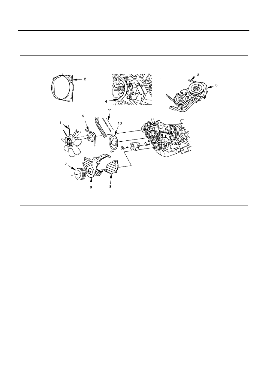
TIMING BELT (4JG2 Belt Type)

Component

Removal

Preparation

• Disconnect battery ground cable.
• Drain coolant.

1. Cooling Fan Assembly

• Remove clamp nut, and remove cooling fan asm,

distant pipe, and fan pulley.

2. Fan Shroud

• Removal reservoir tank hose and fan shroud.

Legend

1. Cooling fan assembly

7. Crankshaft damper pulley

2. Fan shroud

8. Timing pulley upper cover

3. Power steering pump drive belt

9. Timing pulley lower cover

4. A/C compressor drive belt

10. Flange; Camshaft pulley

5. AC Generator drive belt

11. Timing belt

6. Power steering pump bracket assembly

N6A3696E

4JB1/4JB1-TC/4JG2/4JH1-TC - ENGINE 6A1-33

3. Power Steering Pump Drive Belt (P/S Model)

• Loosen power steering pump idle pulley lock nut

and adjust bolt, and remove the drive belt.

4. A/C Compressor Drive Belt (A/C Model)

• Loosen A/C compressor idle pulley lock nut (1) and

adjust bolt (2), and remove the drive belt.

5. AC Generator Drive Belt

• Loosen AC Generator mounting bolt (under side)

and adjust plate lock bolt (1), and remove the drive
belt.

6. Power Steering Pump Bracket Assembly (P/S

Model)

• Loosen power steering oil pipe bracket (1) and clip

(2).

• Remove power steering pump bracket assembly

and hang the power steering pump bracket assem-
bly.

7. Crankshaft Damper Pulley

N6A3223E

N6A3698E

Legend

1. Pipe bracket
2. Clip
3. Lock nut

N6A3699E

N6A3362E

6A1-34 4JB1/4JB1-TC/4JG2/4JH1-TC - ENGINE

8. Timing Pulley Upper Cover
9. Timing Pulley Lower Cover

10. Flange; Camshaft Pulley
11. Timing Belt

• Prepare a fixing bolt (M8 

× 40, P = 1.25)

• Turn crankshaft timing pulley in the normal direc-

tion pulley side mark to timing pulley housing side
mark.

• Make sure that the camshaft pulley and injection

timing pulley fixing bolt holes are set to each other.
Then fit in a fixing bolt (1) and lightly tighten.

• No.1 cylinder should be at top dead center.

If the fixing bolt holes are not set (No.4 cylinder is
at top dead center) give another turn.

• Remove tensioner and timing belt.

Warning:

WARNING:
IF CRANKSHAFT AND CAMSHAFT AND TURNED
WITH TIMING BELT BEING NOT MOUNTED, PISTON
AND VALVE WILL INTERFERE WITH EACH OTHER.
THEREFORE, THE SHAFTS MUST NOT BE
TURNED.

Installation

1. Timing Belt

• When removing the belt, make sure the marks on

the bolt fixed camshaft, injection pulley and crank-
shaft timing pulley are set to each other (1).

Caution:
Do not turn crankshaft because otherwise piston and
valve will interfere with each other.

N6A3159E

N6A3702E

N6A3775E

N6A3704E

4JB1/4JB1-TC/4JG2/4JH1-TC - ENGINE 6A1-35

Caution:
For accurate mounting, be sure to mount the belt in the
direction that letters on the belt are readable.

• Mount new timing belt on pulleys in the following

steps.
Crankshaft timing pulley (1) 

→ Camshaft

Timing pulley (2) 

→ Idle pulley (3) → Injection

Pump pulley (4) 

→ tensioner (5)

• Set the belt on crankshaft timing pulley and hold

with one hand.

• Stretch and pass the belt round each pulley with

the other hand.

• After passing it round injection pump pulley, install

tensioner while taking care not to slacken the belt.

Caution:

• On completion of belt passing, make sure that the

setting mark on crankshaft timing pulley is set.

• If not set, reset the mark and repeat the belt pass-

ing.

• Remove tension adjust, lever mounting bolt, and

loosen the fulcrum bolt to such extent that the lever
is movable.

Legend

1. Cylinder head side

N6A3705E

N6A3706E

Legend

1. Lock bolt
2. Setting mark

N6A3151E

N6A3708E


Content   ..  584  585  586  587   ..