Isuzu N-Series. Manual - part 543
6F-2 Exhaust System
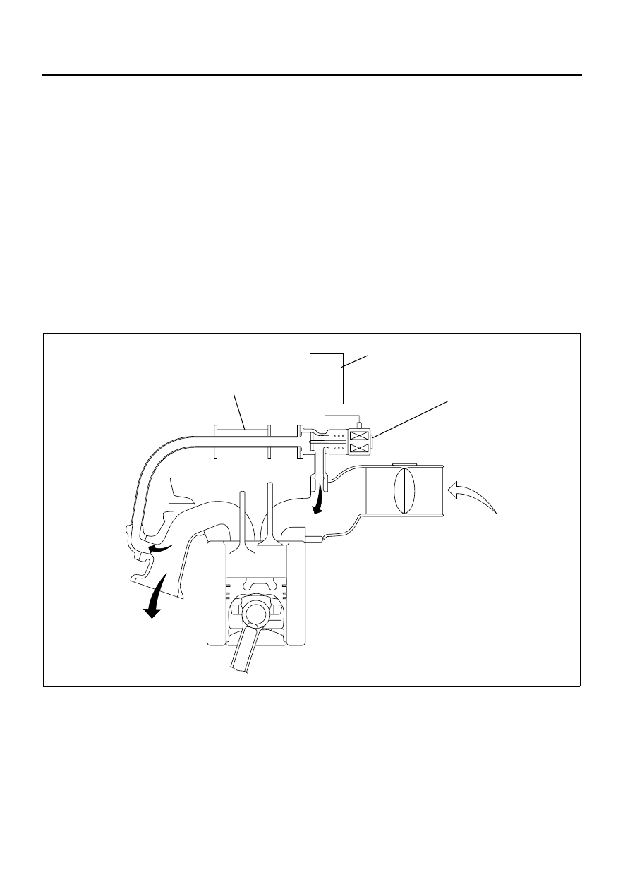
EGR System
Service Precautions
Perform EGR related assembly according to the usual
procedure of temporarily fitting and then permanently
tightening the parts so that unnecessary stresses are
not applied on the parts.
Explanations on Functions and Operation
The EGR system recirculates a part of exhaust gas
back into the intake manifold, which results in reducing
nitrogen oxide (NOx) emissions. The EGR control
system uses an electronic control system to ensure
both driveability and low emission. The control current
from the engine control module (ECM) operates the
motor to control the lift amount of EGR valve. Also, an
EGR position sensor is provided at the rear of the
motor to feed actual valve lift amount back to the ECM
for more precision control of the EGR amount.
The EGR control starts when the conditions for engine
speed, engine coolant temperature and barometric
pressure are satisfied. Then, the valve opening is
calculated according to the engine speed, and target
fuel injection quantity. Based on this valve opening, the
drive duty of the motor is determined and the motor is
driven accordingly.
A potentiometer type EGR valve position sensor is
employed and installed on the EGR valve body. The
EGR valve position sensor is supplied with reference
voltage (5V) and ground at all times from the ECM. The
ECM reads the EGR position sensor voltage input and
determines the EGR lift position.
Legend
1. EGR Cooler
2. ECM
3. EGR Valve
1
2
3
N6A6659E