Isuzu N-Series. Manual - part 542


  Index      Isuzu     Isuzu N-Series - service repair manual


Search            


Content   ..  540  541  542  543   ..


Isuzu N-Series. Manual - part 542


Engine Electrical   6D-35

Preheating System

Glow Plug Replacement
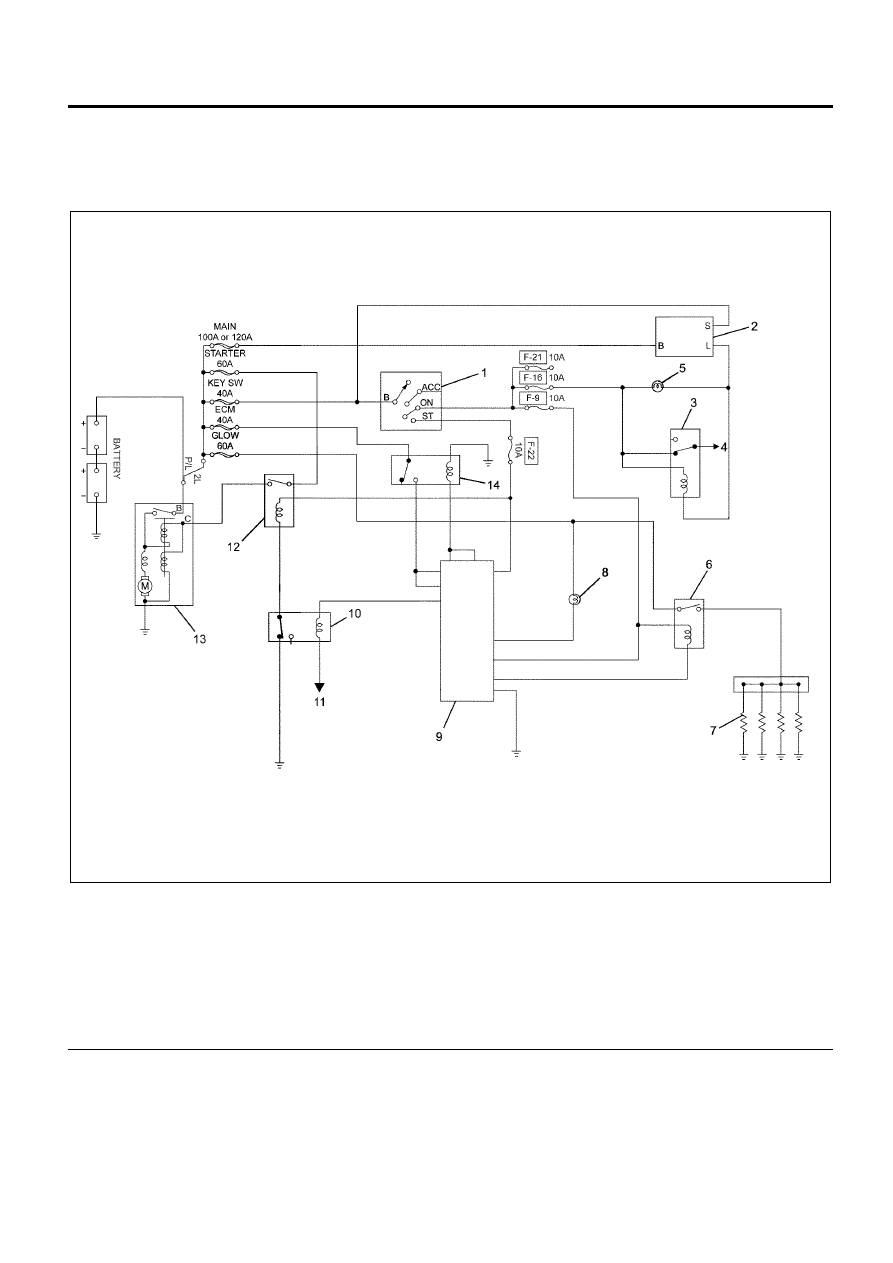
Circuit Diagram

Legend

1. Engine Control Switch
2. Generator (Integral Regulator)
3. Charge Relay
4. To Heater and A/C Relay
5. Low Charge Indicator Light
6. Glow Plug Relay
7. Glow Plugs

8. Glow Plug Indicator Light
9. ECM

10. Starter Cut Relay

11. To Exhaust Brake Solenoid Valve

12. Starter Relay
13. Starter
14. ECM Main Relay

Precautions during maintenance

Adequate care should be taken as over-tightening the
glow plug could lead to damage.

Removal

1. Remove the engine harness, the throttle position

sensor, the EGR valve, the pressure sensor, and
all of the fuel injector connectors.

2. Remove the EGR valve and the EGR adapter.
3. Tape the EGR case holes shut to prevent the entry

of foreign material.

N6A6586E

6D-36   Engine Electrical

Legend

1. EGR Adapter
2. EGR Valve


4. Remove the glow connector.
5. Remove the glow plug.

Installation

1. Install the glow plug.

Tighten:

Glow plug to 20 N

⋅m (2.0 kg⋅m/15 lb⋅ft)

2. Install and tighten the glow connector with the

designated torque.

Tighten:

Glow connector to 12 N

⋅m (1.2 kg⋅m/10 lb⋅ft)

3. Install the EGR valve and the EGR adapter.

Tighten:

EGR valve and adapter to 24 N

⋅m (2.4 kg⋅m/17 lb⋅ft)

Legend

1. EGR Adapter
2. EGR Valve Gasket
3. EGR Valve
4. EGR Valve Gasket


4. Attach the engine harness connectors. Each

composite connector should make a loud click
when it is securely attached.

Service Precautions

Adequate care should be taken as over-tightening the
glow plug could lead to damage.

Explanations on Functions and Operation

The preheating system consists the ECM, the glow
relay, glow plugs and the glow indicator lamp. The
preheating system is operated when the engine coolant
temperature is low, and make the engine easy to start.

Functional check

Refer to Section 6E (Glow Control System Check).
Except the glow plug.

Glow plug check

• Use the circuit tester and measure the resistance

of the glow plug.

• If the measured value deviates from the specified

value, then replace the glow plug.

Resistance value of glow plug is approximately
less than 6

Ω.

Caution:
Use a set of four glow plugs from the same
manufacturer.

N6A6368E

N6A6127E

N6A6371E

Engine Electrical   6D-37

A List of Defective Phenomena

• The glow indicator lamp does not light up.
• Preheating does not work.
• The preheating time is too long or too short.

Trouble Shooting

1. The glow indicator lamp does not light up.

2. Preheating does not work.

3. Preheating time is too long or too short.

Main Data and Specifications

N6A6429E

Condition

Possible Cause

Correction

The glow indicator lamp does not
light up.

Slow blow fuse has blown.

Replace the slow blow fuse.

Fuse is unavailable.

Replace the fuse.

Indicator valve is burnt out.

Replace the indicator valve.

Engine control system is faulty.

Refer to Section 6E.

Condition

Possible Cause

Correction

Preheating does not work.

Slow blow fuse has blown.

Replace the slow blow fuse.

Defective or faulty glow plug relay
connector contact.

Re-mount or replace the glow plug
relay.

Engine control system is faulty.

Refer to Section 6E.

Condition

Possible Cause

Correction

The Preheating time is too long or
too short.

Thermosensor fault and break in
circuit or short circuit.

Replace the thermosensor. Repair
the circuit.

Fault in glow plug.

Replace or tighten the glow plug.

Engine control system is faulty.

Refer to Section 6E.

Preheating device model

Glow plug 

Glow plug rated voltage

(V)

24

Exhaust System   6F-1

ENGINE

Exhaust System

TABLE OF CONTENTS

EGR System . . . . . . . . . . . . . . . . . . . . . . . . . . . . . 6F-2

Service Precautions . . . . . . . . . . . . . . . . . . . . . . 6F-2
Explanations on Functions and Operation . . . . . 6F-2

EGR Valve and EGR Cooler . . . . . . . . . . . . . . . . . 6F-3

Components. . . . . . . . . . . . . . . . . . . . . . . . . . . . 6F-3
Removal . . . . . . . . . . . . . . . . . . . . . . . . . . . . . . . 6F-3
Inspection. . . . . . . . . . . . . . . . . . . . . . . . . . . . . . 6F-4
Installation  . . . . . . . . . . . . . . . . . . . . . . . . . . . . . 6F-4
Torque Specifications . . . . . . . . . . . . . . . . . . . . . 6F-6

Exhaust System  . . . . . . . . . . . . . . . . . . . . . . . . . . 6F-7

Service Precautions . . . . . . . . . . . . . . . . . . . . . . 6F-7
Explanations on Functions and Operation . . . . . 6F-7
Functional Check . . . . . . . . . . . . . . . . . . . . . . . . 6F-7
List of Abnormal Phenomena. . . . . . . . . . . . . . . 6F-7
Trouble Shooting  . . . . . . . . . . . . . . . . . . . . . . . . 6F-8

Exhaust Pipe . . . . . . . . . . . . . . . . . . . . . . . . . . . . . 6F-9

Removal . . . . . . . . . . . . . . . . . . . . . . . . . . . . . . . 6F-9
Inspection. . . . . . . . . . . . . . . . . . . . . . . . . . . . . . 6F-9
Installation  . . . . . . . . . . . . . . . . . . . . . . . . . . . . . 6F-9
Torque Specifications . . . . . . . . . . . . . . . . . . . . 6F-10

Exhaust Brake System . . . . . . . . . . . . . . . . . . . . 6F-11

Service Precautions . . . . . . . . . . . . . . . . . . . . . 6F-11
Explanations on Functions and Operation . . . . 6F-11
Functional Check . . . . . . . . . . . . . . . . . . . . . . . 6F-11

Exhaust Brake. . . . . . . . . . . . . . . . . . . . . . . . . . . 6F-12

Components. . . . . . . . . . . . . . . . . . . . . . . . . . . 6F-12
Removal . . . . . . . . . . . . . . . . . . . . . . . . . . . . . . 6F-12
Disassembly. . . . . . . . . . . . . . . . . . . . . . . . . . . 6F-12
Reassembly . . . . . . . . . . . . . . . . . . . . . . . . . . . 6F-12
Inspection. . . . . . . . . . . . . . . . . . . . . . . . . . . . . 6F-13
Installation  . . . . . . . . . . . . . . . . . . . . . . . . . . . . 6F-13
Torque Specifications . . . . . . . . . . . . . . . . . . . . 6F-14


Content   ..  540  541  542  543   ..