Isuzu N-Series. Manual - part 502


  Index      Isuzu     Isuzu N-Series - service repair manual


Search            


Content   ..  500  501  502  503   ..


Isuzu N-Series. Manual - part 502


Engine Mechanical (4HK1-TC)   6A-113

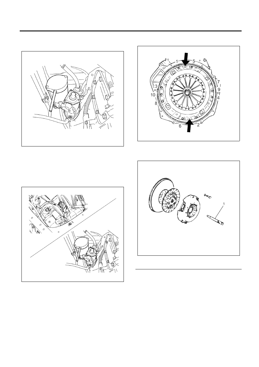
• Disconnect the front frame harness connector

near the control box of the transmission,
remove the clips that fix the harness.

• Remove the two bolts on the upper side and

lower side that fix the starter, remove the starter
from the clutch housing.

• Use wire to secure the starter to the

transmission. Position the wire and starter so
that it does not interfere with the transmission
removal procedure.

2. Remove the transmission assembly.

Refer to “Engine Assembly”.

3. Remove the clutch pressure plate assembly.

• Insert the clutch aligner on the spline of the

driven plate.

• Remove the clutch pressure plate assembly

installation bolts in the order shown in the
drawing.

• Remove the clutch pressure plate assembly

from the flywheel.

4. Remove the clutch plate assembly.

• Remove the clutch plate assembly from the

flywheel along with the clutch aligner (1).

Legend

1. Clutch Aligner


• Install the crankshaft stopper in the starter

installation part of the flywheel housing.

Caution:
Make sure that the stopper is applied with the ring gear
and installed properly.

N6A6215E

N6A6216E

N6A6217E

N6A6218E

6A-114   Engine Mechanical (4HK1-TC)

Special tool
Crankshaft stopper: 5-8840-2230-0 (EN-47680)

5. Remove the crankshaft position sensor.

• Remove to prevent contact damage when the

flywheel is removed.

• Do not throw or drop because it is vulnerable to

shock.

6. Remove the washer.
7. Remove the flywheel.

• Gradually loosen the flywheel installation bolts

in the order shown in the drawing so that the
flywheel does not rotate.

• After loosening the bolts, remove the stopper

and remove the flywheel.

• In the case of smoother vehicle, after loosening

the flexible plate installation bolts, remove the
washer, flexible plate, spacer in this order.

8. Remove the pilot bearing.

• Remove the pilot bearing from the flywheel.

Legend

1. Washer
2. Pilot Bearing
3. Flywheel


9. Remove the ring gear.

N6A6057E

N6A6056E

N6A6078E

N6A6219E

Engine Mechanical (4HK1-TC)   6A-115

• Put a bar on the ring gear and hit it with a

hammer to remove it.

Inspection

1. Inspection with eyes

• Inspect the flywheel friction surface for cracks

and damages, and replace it if it has
abnormality.

• Inspect the tooth part of the ring gear, replace

the ring gear if it has damage or serious wear.

2. Measurement of the friction surface

• Measure the depth of the friction surface of the

flywheel.

• Adjust it if the measured value is between the

standard value and the limit.

• If the measured value exceeds the limit, replace

the flywheel.

Depth = From the pressure installation surface
to the friction surface.

Installation

1. Install the ring gear.

• After heating the ring gear with a gas burner

equally, install it in the flywheel.

• During shrinkage cooling of the ring gear,

maintain the flatness by applying force of
68.6 kN (15,400 lbf).

Caution:

• Install the ring gear in the direction within the

chamfered face comes to the side of pressure
installation surface.

• Shrink fit the ring gear to the flywheel.

Make sure that flywheel and ring gear adhesion is
complete.

2. Install the flywheel.
3. Install the washer.

Depth of the friction surface of the 
flywheel

mm (in)

Standard

19 (0.75 )

Limit

20 (0.79)

N6A6220E

N6A6221E

N6A6222E

6A-116   Engine Mechanical (4HK1-TC)

M/T specification

1) Align the flywheel with the crankshaft knock pin

and temporarily tighten the flywheel bolts.

2) Use the crankshaft stopper to prevent the

crankshaft from turning.
Crankshaft stopper: 5-8840-2230-0 (EN-47680)

• Apply molybdenum disulfide on the thread and

setting face of the bolt.

3) Install the washer and the flywheel bolts and

tighten to the specified torque in numerical order
show in the illustration.

Tighten:
Bolts to
1st step: 78 N

⋅m (8.0 kg⋅m/58 lb⋅ft)

2nd step: 120

° – 150° (degrees)

Special tool
Crankshaft stopper: 5-8840-2230 (EN-47680)
Angle gauge: 5-8840-0266-0 (J-45059)

Smoother specification

1) Align the knock pin on the crankshaft to install

the spacer.

2) Install the flexible plate and washer, also

aligning to the knock pin on the crankshaft.

3) Apply molybdenum disulfide grease to the bolt

thread and seat to install the flywheel fixing hole. 
Tighten bolt to two stage tightening method in
the numerical order.
1st step; 78 N

⋅m (8.0 kg⋅m/58 lb⋅ft)

2nd step; 90

° – 120° (degrees)

4. Install and tighten the crankshaft position sensor

with the designated torque.

Tighten:
Bolt to 8 N

⋅m (0.8 kg⋅m/69 lb⋅in)

5. Hammer in the pilot bearing until it reaches the

edge surface of the crank.

6. Install the clutch plate assembly.

N6A6078E

N6A6057E

N6A6078E


Content   ..  500  501  502  503   ..