Isuzu N-Series. Manual - part 475
Engine Mechanical (4HK1-TC) 6A-5
Crankshaft
Tuftriding is given, while on the No. 1 balance weight
imprinted is the grade of each journal diameter.
EGR System
Based upon data, including water temperature, engine
speeds or engine loads, it is controlled via Engine
Control Module (ECM) to purify exhaust by recycling
part of it.
Its main components include an EGR valve, an EGR
cooler and various sensors.
Connecting Rod Cap Bolt
The angular tightening method of the connecting rod
cap bolt further increases reliability and durability.
Common Rail-type Electronic Control Injection
System
The common rail-type electronic control injection
system is composed of a fuel supply pump that sets the
target pressure of high-pressure fuel and supply it, a
fuel rail that measures such high-pressure fuel and an
fuel injector that turns it into a fine spray and injects it.
Each is controlled via ECM based upon various
signals, while injection timing or fuel injection quantity
is controlled under every possible driving condition.
Fuel Injector
The fuel injector is a 7-hole nozzle that adjusts fuel
injection quantity or injection timing by opening or
closing an electromagnetic valve on the head of the
fuel injector.
ECM corrects the dispersion of fuel injection quantity
between fuel injectors according to ID code data in
memory. At the replacement of fuel injectors, ID code
data should be stored in ECM.
Fuel Filter with Sedimenter
It is a fuel filter with sedimenter that gets rid of water by
making use of the difference in specific gravity between
light oil and water, which comes with an indicator that
notifies you that it is filled with water.
Preheating System
The preheating system consists the ECM, the glow
relay, glow plugs and the glow indicator lamp. The
preheating system is operated when the engine coolant
temperature is low, and make the engine easy to start.
Lubrication System
It is an oil filter with full-flow bypass, which uses a
water-cool oil cooler and oil jet to cool the piston.
Functional Inspection
Inspection/adjustment of valve clearance
1. Inspection of valve clearance
a. Remove the cylinder head cover.
b. Remove the fuel injector harness assembly.
c. Loosen the terminal nuts alternately to remove.
d. Remove the leak-off pipe.
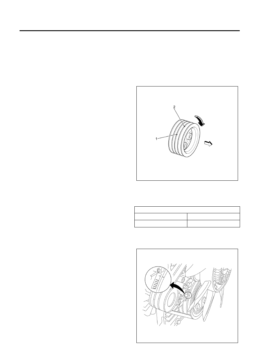
e. Rotate the crankshaft to make the No.1 cylinder
meet the compression top dead center (TDC).
Notice:
There are 2 timing marks on the crankshaft pulley.
Mark (1) is near the cylinder block and is used to bring
the 4HK1-TC engine to TDC.
Mark (2) is not applicable to this engine.
Be sure to use mark (1) when bringing the engine to
TDC.
• Insert a 0.4 mm (0.016 in) thickness gauge into
a clearance between the rocker arm and the
bridge to check it and adjust it if needed.
Caution:
Adjust while being cold.
Valve clearance
mm (in)
Intake valve
0.4 (0.016)
Exhaust valve
0.4 (0.016)
N6A6002E
N6A6003E