Isuzu N-Series. Manual - part 453


  Index      Isuzu     Isuzu N-Series - service repair manual


Search            


Content   ..  451  452  453  454   ..


Isuzu N-Series. Manual - part 453


6E-148 EMISSION AND ELECTRICAL DIAGNOSIS
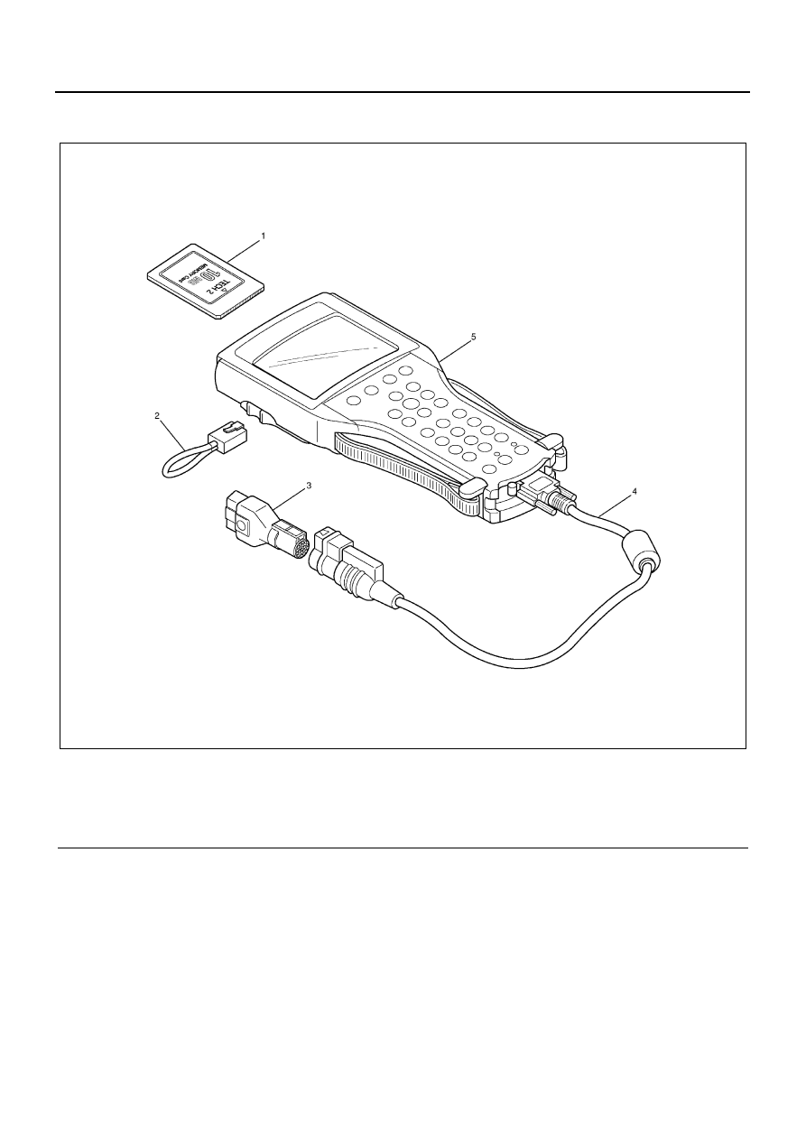
SPECIAL TOOLS

Legend

1. PCMCIA card

4. DLC cable

2. RS232 loop back connector

5. TECH-2

3. SAE 16/19 adapter

N6A1293E

EMISSION AND ELECTRICAL DIAGNOSIS 6E-149

Illustration

Tool Number / 

Description / Remarks

5-8840-0366-0 (J 39200) 

/ High Impedance Multi-

meter (Digital Voltmeter- 

DVM)

1. PCMCIA Card

2. RS232 Loop Back

3. SAE 16/19 Adapter

4. DLC Cable

5. TECH-2

5-8840-0279-0 (J 23738-

A) / Vacuum Pump with 

Gauge

5884003660

N6A1295E

5884002790

6E-150 EMISSION AND ELECTRICAL DIAGNOSIS

DIAGNOSIS (4HG1-T Only)

Strategy-Based Diagnostics

Strategy-Based Diagnostics
The strategy-based diagnostic is a uniform approach to
repair all Electrical/Electronic (E/E) systems. The diag-
nostic flow can always be used to resolve an E/E system
problem and is a starting point when repairs are neces-
sary. The following steps will instruct the technician how
to proceed with a diagnosis:

1. Verify the customer complaint.

• To verify the customer complaint, the techni-

cian should know the normal operation of the
system.

2. Perform preliminary checks.

• Conduct a thorough visual inspection.
• Review the service history.
• Detect unusual sounds or odors.
• Gather diagnostic trouble code information to

achieve an effective repair.

3. Check bulletins and other service information.

• This includes videos, newsletters, etc.

4. Refer to service information (manual) system

check (s).

• “System checks” contain information on a sys-

tem that may not be supported by one or more
DTCs. 
System checks verify proper operation of the
system. This will lead the technician in an orga-
nized approach to diagnostics.

5. Refer to service diagnostics.

Diagnostic Trouble Code (DTC) Stored
Follow the designated DTC chart exactly to make an ef-
fective repair.
No DTC
Select the symptom from the symptom tables. 
Follow the diagnostic paths or suggestions to complete
the repair. You may refer to the applicable component/
system check in the system checks.
No Matchig Symptom

1. Analyze the complaint.
2. Develop a plan for diagnostics.
3. Utilize the wiring diagrams and the theory of oper-

ation.

Call technical assistance for similar cases where repair
history may be available. Combine technician knowl-
edge with efficient use of the available service informa-
tion.
Intermittents
Conditions that are not always present are called inter-
mittents. To resolve intermittents, perform the following
steps:

1. Evaluate the symptoms and the conditions de-

scribed by the customer.

2. Use a check sheet or other method to identify the

circuit or electrical system component.

3. Follow the suggestions for intermittent diagnosis

found in the service documentation.

No Trouble Found
This condition exists when the vehicle is found to oper-
ate normally. The condition described by the customer
may be normal. Verify the customer complaint against
another vehicle that is operating normally. The condition
may be intermittent. Verify the complaint under the con-
ditions described by the customer before releasing the
vehicle.

1. Re-examine the complaint When the Complaint

cannot be successfully found or isolated, a re-eval-
uation is necessary. 
The complaint should be re-verified and could be
intermittent as defined in Intermittents, or could be
normal.

2. Repair and verify. 

After isolating the cause, the repairs should be
made. 
Validate for proper operation and verify that the
symptom has been corrected. This may involve
road testing or other methods to verify that the
complaint has been resolved under the following
conditions:

• Conditions noted by the customer.
• If a DTC was diagnosed, verify a repair by duplicat-

ing conditions present according to customer com-
plaint.

Verifying Vehicle Repair
Verification of the vehicle repair will be more compre-
hensive for vehicles with self diagnostic system diag-
nostics. Following a repair, the technician should
perform the following steps:

Important:
Follow the steps below when you verify repairs on self
diagnostic systems. Failure to follow these steps could
result in unnecessary repairs.

1. Review and record the Failure Records for the

DTC which has been diagnosed.

2. Clear the DTCs.
3. Operate the vehicle within conditions according to

customer complaint.

4. Monitor the Diagnostic Trouble Code (DTC) status

information for the specific DTC which has been di-
agnosed until the diagnostic test associated with
that DTC runs.

EMISSION AND ELECTRICAL DIAGNOSIS 6E-151

GENERAL SERVICE INFORMATION

Visual/Physical Engine Compartment Inspection
Perform a careful visual and physical engine compart-
ment inspection when performing any diagnostic proce-
dure or diagnosing the cause of an emission test failure.
This can often lead to repairing a problem without further
steps. Use the following guidelines when performing a
visual/physical inspection:

• Inspection all vacuum hoses for punches, cuts, dis-

connects, and correct rouring.

• Inspect hoses that are difficult to see behind other

components.

• Inspect all wires in a engine compartment for prop-

er connections, burned or chafed spots, pinched
wires, contact with sharp edges or contact with hot
exhaust manifolds or pipes.

Basic Knowledge of Tools Required

Notice:
Lack of basic knowledge of this powertrain when per-
forming diagnostic procedures could result in an incor-
rect diagnosis or damage to powertrain components. Do
not attempt to diagnose a powertrain problem without
this basic knowledge.
A basic understanding of hand tools is necessary to ef-
fectively use this section of the Servise Manual
Self Diagnostic System Check
Self Diagnostic System should be checked as follows:

1. When Ignition key is turned from the “OFF” to the

“ON” position, make sure that Malfunction Indicator
Lamp (MIL) is lit for 0.3 — 0.8 sec.

2. Connect Scan Tool and check to see if MIL is al-

ways lit.
If so, Self Diagnostic System is normal.


Content   ..  451  452  453  454   ..