Isuzu N-Series. Manual - part 439


  Index      Isuzu     Isuzu N-Series - service repair manual


Search            


Content   ..  437  438  439  440   ..


Isuzu N-Series. Manual - part 439


6E-92 EMISSION AND ELECTRICAL DIAGNOSIS

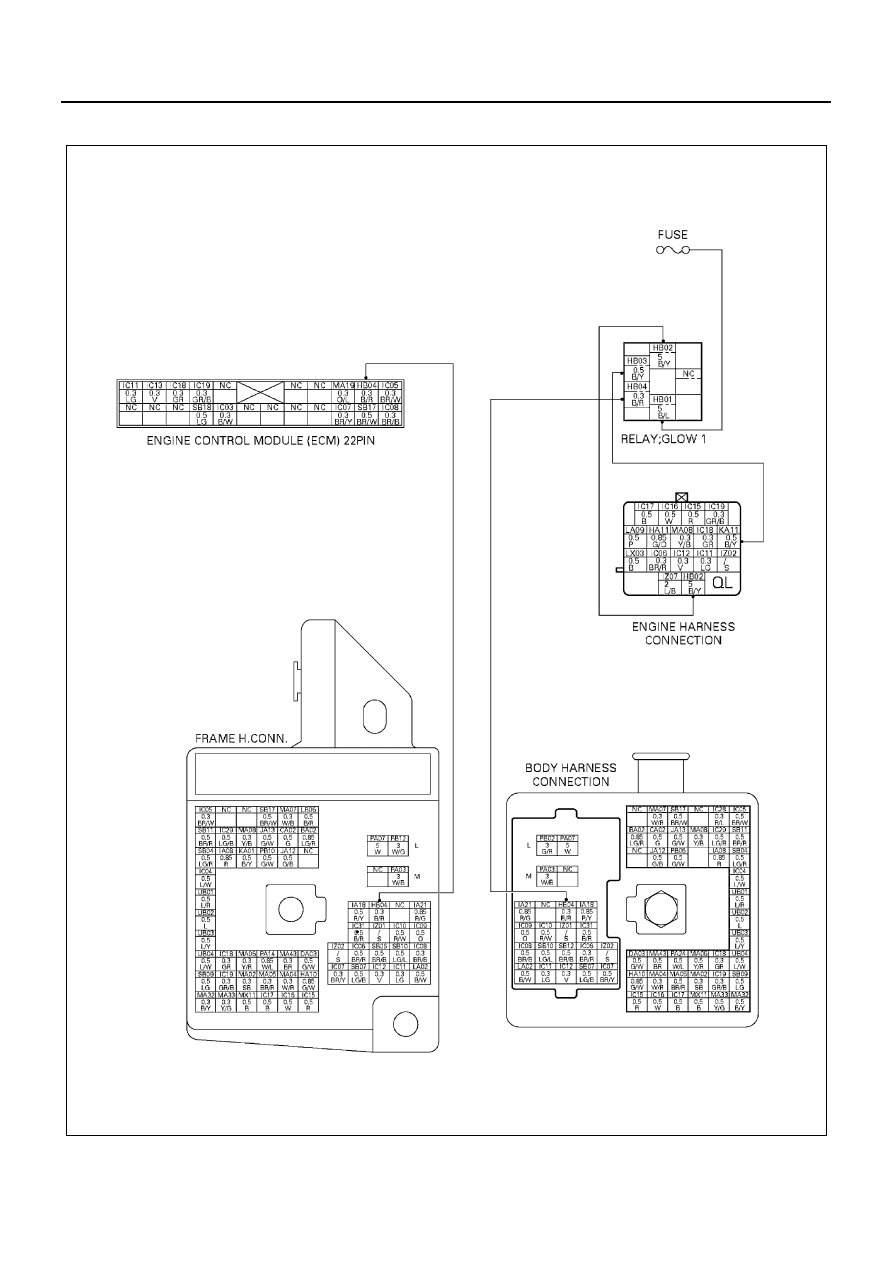
DTC-P41 Quick On Start (QOS) Relay Control Circuit Low Voltage

N6A1212E

EMISSION AND ELECTRICAL DIAGNOSIS 6E-93

Location of Relay

Legend

1. Relay box (Installed on the left side rear of the 

cab)

N6A1184E

NO

RELAY NAME

X-20

Glow plug

X-21

Starter

X-22

Marker lamp

X-23

Rear fog

X-24

A/C COMP, 4WD ind. lamp

X-25

Exh, Brake control

X-26

CSD, A/C ON SIGNAL

X-27

Condenser fan

X-28

Exh. Brake cut

6E-94 EMISSION AND ELECTRICAL DIAGNOSIS

Inspection for quick on start (QOS) power cut relay

Resistance value

Legend

A. QOS relay

N6A1214E

Legend

A. QOS relay

N6A1215E

Inspection Point

Resistance

Reference

Inspection 
relay unit

←→  5

23  (

Ω) (for 12 volt)

100 (

Ω) (for 24 volt)

←→ 3

Not be supplied electricity to coil

Below 0.5 (

Ω)

Be supplied electricity to coil

EMISSION AND ELECTRICAL DIAGNOSIS 6E-95

Step

Action

Value

YES

NO

1

Was the “on-board diagnostic (OBD) system
check” performed?

Go to Step 2

Go to self diag 

system check

2

1. Ignition “OFF”
2. Disconnect the Relay from the Relay box

connector.

3. Ignition “ON” Engine “OFF”
4. Using the Digital Voltmeter (DVM), check

for voltage on the “HBOL” terminal of the
Relay Box Connector.

Does the DVM read the following value?

12 Volt or 24 

Volt

Go to Step 4

Go to Step 3

3

1. Check the suspect circuit between the

Relay connector.
Fuse for the following condition.

• A short to ground
• An open circuit

2. Repair if necessary.

Has DTC 41 been corrected?

Go to Step 8

Go to Step 4

4

Using the DVM, check the resistance of inter
“4” “5” Relay terminal.

Does the DVM read the following Value?

23

Ω (for 12 

Volt)

100

Ω (for 24 

Volt)

Go to Step 5

Go to Step 6

5

1. Ignition “OFF”
2. Disconnect the ECM connector from

ECM.

3. Check the VSV circuit between the ECU

and Relay connector.

• A short to ground
• An open circuit

4. Repair if necessary.

Has DTC 41 been corrected?

Go to Step 8

Go to Step 7

6

Replace the Relay.

Is the action complete?

Go to Step 8

7

Replace the ECM.

Is the action complete?

Go to Step 8

8

1. Reconnect all the connectors removed.
2. Ignition “ON”, Engine “OFF”

Is DTC 41 all right under Scan Tool Check?

Go to Step 9

Go to Step 2

9

Is any current trouble other than DTC 41 dis-
played by scan tool?

Go to trouble code 

section

Trouble code clear


Content   ..  437  438  439  440   ..