Isuzu N-Series. Manual - part 437


  Index      Isuzu     Isuzu N-Series - service repair manual


Search            


Content   ..  435  436  437  438   ..


Isuzu N-Series. Manual - part 437


6E-84 EMISSION AND ELECTRICAL DIAGNOSIS
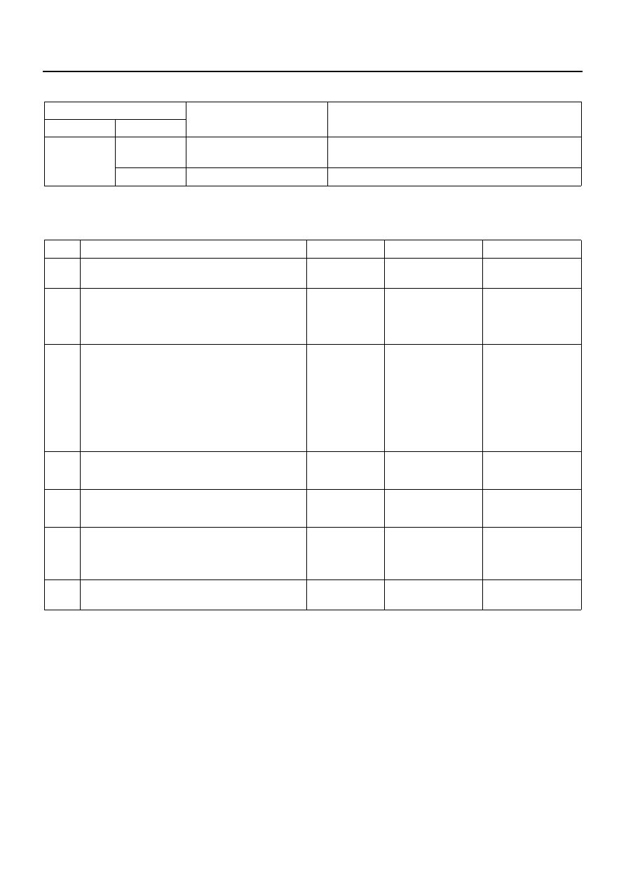
Resistance value

Notice:
Resistance value is difference according to the engine temperature (condition of engine warming up).

Inspection Point

Resistance Value

(k

Ω)

Reference

Connector

Pin No.

2 pin Gray

←→ 1

37 to 44 (for 12 volt)

159 to 169 (for 24 volt)

SIG 

←→ GND

←→ Body

SIG 

←→ Body

Step

Action

Value

YES

NO

1

Was the “on-board diagnostic (OBD) system
check” performed?

Go to Step 2

Go to self diag 

system check

2

Using the DVM, check the resistance of the
VSV.

Does the DVM read the following Value?

37 — 44

Ω (for 

12 Volt)

159 — 169

Ω 

(for 24 Volt)

Go to Step 3

Go to Step 4

3

1. Ignition “OFF”
2. Disconnect the ECM connector from

ECM.

3. Check the short to voltage of VSV circuit

between the ECM and VSV connector

4. Repair if necessary.

Has DTC 34 been corrected?

Go to Step 6

Go to Step 5

4

Replace the VSV.

Is the action complete?

Go to Step 6

5

Replace the ECM.

Is the action complete?

Go to Step 6

6

1. Reconnect all the connectors removed.
2. Ignition “ON”, Engine “OFF”

Is DTC 34 all right under Scan Tool Check?

Go to Step 7

Go to Step 2

7

Is any current trouble other than DTC 34 dis-
played by scan tool?

Go to trouble code 

section

Trouble code clear

EMISSION AND ELECTRICAL DIAGNOSIS 6E-85

DTC-P35 Exhaust Gas Recirculation (EGR) Quick Cut Vacuum Switching Valve (VSV) Con-
trol Circuit Low Voltage

N6A1204E

6E-86 EMISSION AND ELECTRICAL DIAGNOSIS

Appearance of Vacuum Switching Valve (VSV):
Exhaust Gas Recirculation (EGR) CUT and
Connector Name

VSV: EGR CUT

VSV: EGR CUT Connector

Measure Resistance at VSV: EGR CUT

Caution:
When measuring resistance with a circuit tester, be careful not to damage or deform the terminals.

N6A1205E

Legend

1. To VSV: EGR
2. 2 pin

Connector No

Signal

1

SIG

2

GND

N6A1190E

Legend

1. Circuit tester

3. Measure resistance between connector pin

2. Remove VSV wire harness

N6A1207E

EMISSION AND ELECTRICAL DIAGNOSIS 6E-87

Resistance value

Notice:
Resistance value is difference according to the engine temperature (condition of engine warming up).

Inspection Point

Resistance Value

(k

Ω)

Reference

Connector

Pin No.

2 pin Black

←→ 1

37 to 44 (for 12 volt)

159 to 169 (for 24 volt)

SIG 

←→ GND

←→ Body

SIG 

←→ Body


Content   ..  435  436  437  438   ..