Isuzu N-Series. Manual - part 412
6D3-16 CHARGING SYSTEM
The valve must move smoothly.
If it does not, the check valve must be replaced.
2) Apply compressed air to the “A” side.
Check for air leakage from the check valve.
If there is air leakage, the valve must be re-
placed.
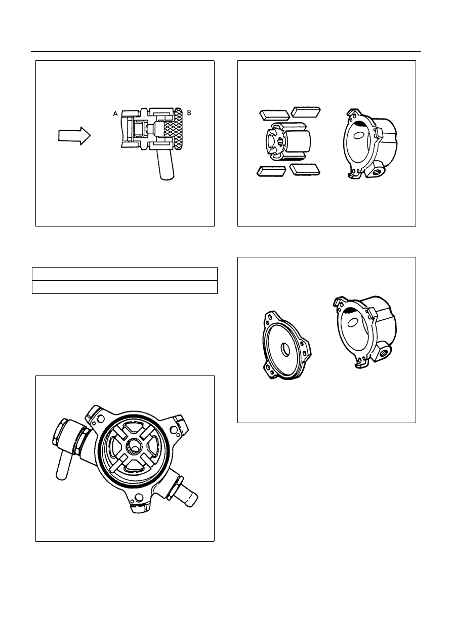
Reassembly
1. Install the vanes to the rotor slits.
The rounded side of the vanes must be facing the
rotor housing.
2. Install the rotor with the concave side facing the
center plate.
3. Install the center plate to the rotor housing.
Be sure to use a new O-rings.
Reassembly
1. Rear Cover
2. Brush and IC Regulator
3. Rectifier
4. Fan Guide
5. Stator
Air Pressure
kPa (kg/cm
2
/psi)
98 — 490 (1 — 5/14.22 — 71.10)
N6A1069E
N6A1070E
N6A1071E
N6A1067E