Isuzu N-Series. Manual - part 410
6D3-8 CHARGING SYSTEM
UNIT REPAIR
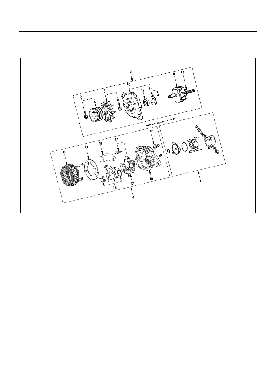
Component
Legend
1. Vacuum pump assembly
11. Bearing retainer
2. Through bolt
12. Front ball bearing
3. Rotor and front cover assembly
13. Rear ball bearing
4. Stator and rear cover assembly
14. Terminal nut and bolt
5. Pulley nut
15. Stator
6. Pulley
16. Fan guide
7. Fan
17. Rectifier
8. Spacer
18. Brush and IC regulator
9. Rotor
19. Rear cover
10. Front cover
N6A1043E