Isuzu N-Series. Manual - part 386


  Index      Isuzu     Isuzu N-Series - service repair manual


Search            


Content   ..  384  385  386  387   ..


Isuzu N-Series. Manual - part 386


6C-22 FUEL SYSTEM

2. Full needle valve lift confirmation

• Confirm the full needle valve lift in accordance

with the closed method.

3. Pre-lift confirmation

• Confirm pre-lift in accordance with the closed

method.

Caution:
If not as specified, replace the nozzle assembly, lift
piece, pins and spacer using the nozzle service kit.

4. Second nozzle opening pressure confirmation

• Confirm the second nozzle opening pressure in

accordance with the closed method.

5. Second nozzle opening pressure adjustment

• Adjust the second nozzle opening pressure us-

ing the shim.

6. Final inspection

• Confirm the condition of the fuel spray with the

nozzle and nozzle holder assembled.

Adjustment Service Data (4HG1-T only)

First nozzle opening pressure adjustment

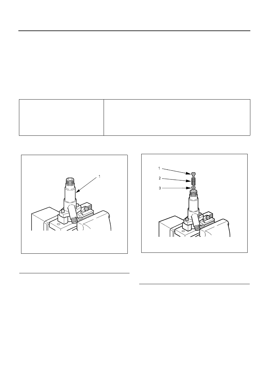
1. Clamp the nozzle holder in a vise.

2. Install the shim, first spring and spring seat in the

nozzle holder.

Nozzle needle valve full-lift

0.30 mm (0.0118 in)

Nozzle needle valve pre-lift

0.04 mm (0.0016 in) at 19.1 MPa (195 kg/cm

2

, 2,770 psi)

Nozzle pressure

1st Stage

18.1 MPa (185 kg/cm

2

, 2,630 psi)

2nd Stage

22.1 — 23.0 MPa (225 — 235 kg/cm

2

, 3,200 — 3,342 psi) at lift 0.09 

mm (0.0035 in) = pre lift + 0.05 mm (0.0020 in)

Legend

1. Nozzle holder body

N6A0860E

Legend

1. Spring seat
2. First spring
3. First nozzle opening pressure adjusting shim

N6A0861E

FUEL SYSTEM 6C-23

3. Install the collar, second spring, shim, spring seat

and push rod in the nozzle holder.

4. Install the pins (1), lift piece (2) and spacer (3) in

the nozzle holder.

5. Install the pins (1) in the spacer.
6. Install the nozzle (2) on the spacer.

7. Hand-tighten the adjustment retaining nut together

with the gasket to the nozzle holder.
Retaining nut: 157892-3200 (* Bosch AS)
Gasket: 157892-5100 (* Bosch AS)
(* Bosch Automotive System Corporation)

8. Tighten the adjustment retaining nut to the speci-

fied torque.
Torque: 29 — 39 N

⋅m (3.0 — 4.0 kg⋅m/257 — 345

lb

⋅in)

Legend

1. Second nozzle opening pressure adjusting 

shim

2. Second spring
3. Collar
4. Push rod
5. Spring seat

N6A0862E

N6A0863E

Legend

1. Retaining nut (special tool)
2. Gasket
3. Nozzle

N6A0864E

N6A0865E

6C-24 FUEL SYSTEM

9. Set the nozzle holder (1) to the nozzle tester (2).

10. Operate the nozzle tester and measure the first

nozzle opening pressure.

11. If the first nozzle opening pressure is not as speci-

fied, disassemble the nozzle holder and replace
the shim until the pressure is as specified.

Caution:

• Use a micrometer to measure shim thickness.
• Use some combination of 3 adjusting shims to ad-

just the pressure.

• First nozzle opening pressure adjusting shims

Full Needle Valve Lift Confirmation

1. Install the gasket (1) and plug (2) on the adjust-

ment retaining nut.
Gasket:
026508-1140 (Bosch AS)
894227-6020 (ISUZU)
Plug:
157892-1600 (Bosch AS)

Legend

1. Torque wrench
2. Retaining nut (special tool)

N6A0866E

N6A0867E

Part No. (ISUZU)

Thickness mm (in)

115349-0420

0.40 (0.0157)

115349-0430

0.50 (0.0197)

115349-0440

0.52 (0.0205)

115349-0450

0.54 (0.0213)

115349-0460

0.56 (0.0220)

115349-0470

0.58 (0.0228)

115349-0480

0.60 (0.0236)

115349-0490

0.70 (0.0276)

Legend

1. Thickness

N6A1649E

FUEL SYSTEM 6C-25

2. Position the nozzle holder with the nozzle facing

down and install the dial gauge holder on the noz-
zle holder.
Dial gauge holder: 157892-5000 (Bosch AS)

3. Install the nut on the dial gauge holder.

Nut: 157892-1000 (Bosch AS)

4. Install the pin (1) to the dial gauge (2).

Notice:
The lengths of the pins do not include the threaded por-
tions.

Pin (l=100 mm (3.94 in)):
157892-5200 (Bosch AS)
Dial gauge:
157954-3800 (Bosch AS)
185317-0150 (ISUZU)

5. Secure the dial gauge to the nozzle holder using

the nut so that the pin contacts the tip of the first
spring seat.

Legend

1. Holder (special tool)

N6A0869E

N6A0870E

Legend

1. Nut (special tool)
2. Holder (special tool)

N6A0871E

N6A0872E


Content   ..  384  385  386  387   ..