Isuzu N-Series. Manual - part 385
6C-18 FUEL SYSTEM
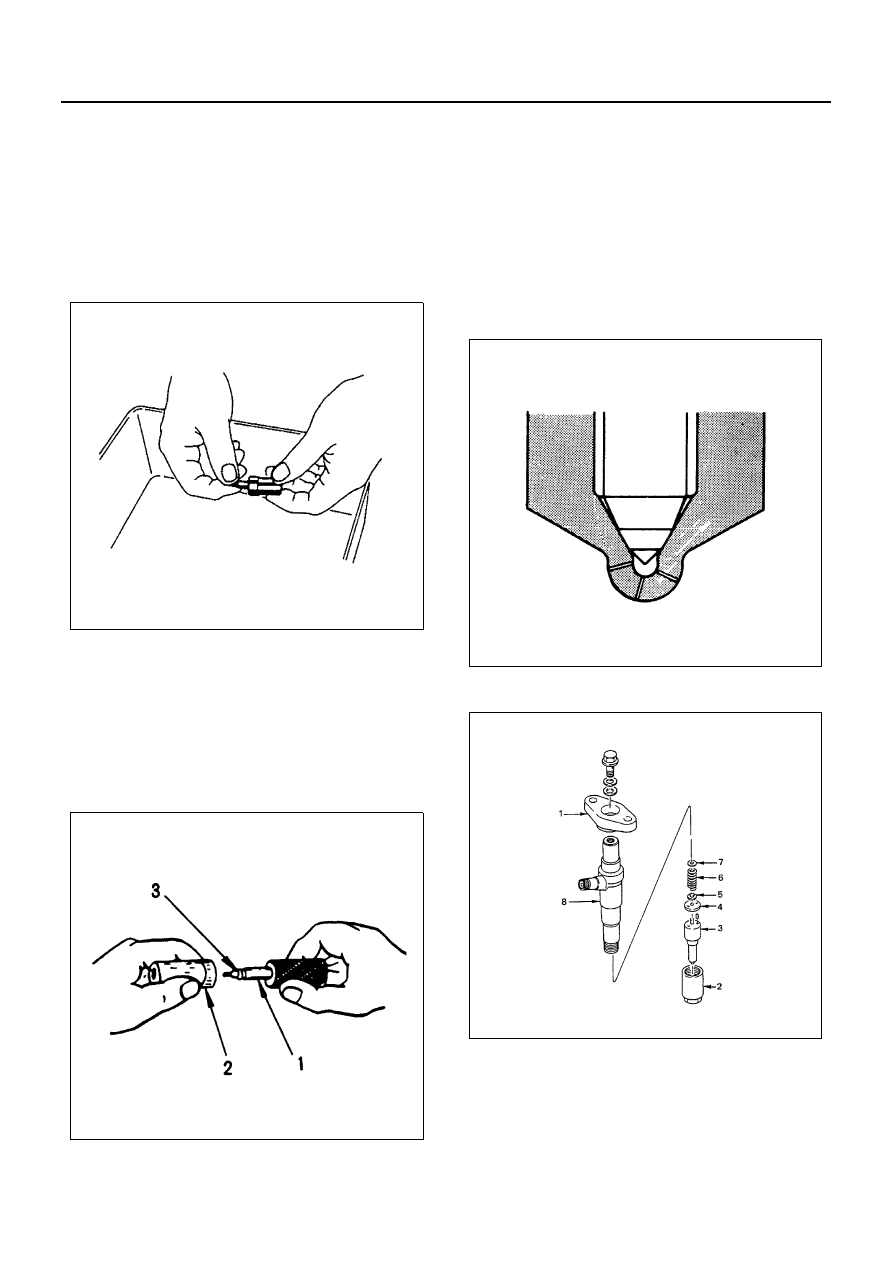
Inspection
Injection Nozzle Needle
1. Remove the nozzle from the nozzle body.
2. Carefully wash the nozzle needle and the nozzle
body in clean diesel fuel.
3. Check that the nozzle needle moves smoothly in-
side the injection nozzle body.
If the nozzle does not move smoothly, it must be
repaired (See “Nozzle Lapping Procedure” below).
Nozzle Lapping Procedure
1. Lap the nozzle needle (1) and the nozzle body (2)
by applying a compound of oxidized chrome and
animal oil (3).
Notice:
Do not apply an excessive amount of the oxidized
chrome and animal oil compound to the injection needle
valve seat area.
2. Carefully wash the needle valve and the nozzle
body in clean diesel fuel after lapping.
Nozzle Body and Needle Valve
Check the nozzle body and the needle valve for damage
and deformation.
The nozzle and body assembly must be replaced if ei-
ther of these two conditions are discovered during in-
spection.
Notice:
New nozzles must be cleaned in a solvent to remove
protective coating.
The nozzle body and needle must always be replace as
an assembly.
Reassembly
N6A0847E
N6A0850E
N6A0845E