Isuzu N-Series. Manual - part 378
6B-6 ENGINE COOLING
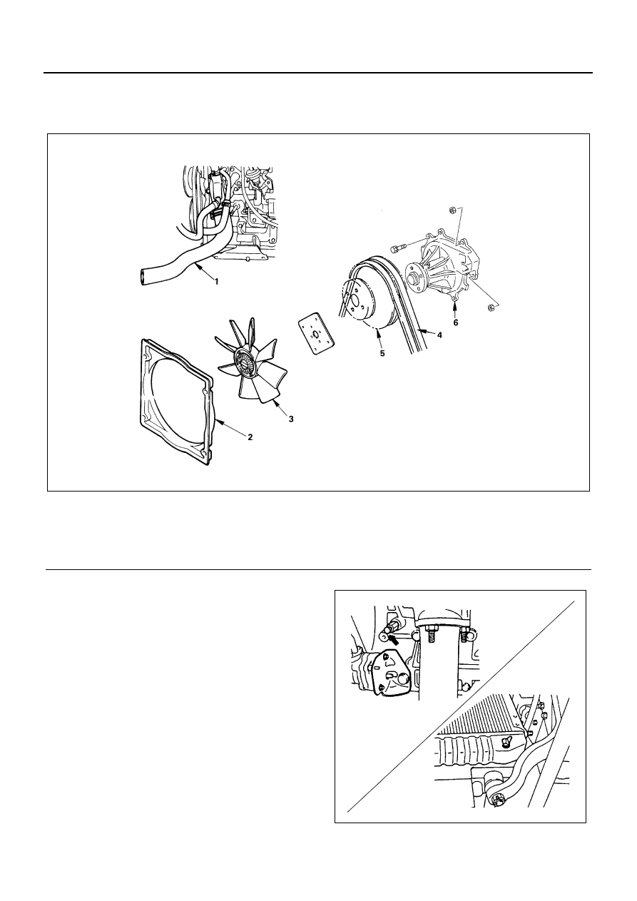
WATER PUMP
Component
Removal
Preparation
• Disconnect battery ground cable.
• Drain coolant.
• Tilt the cab.
1. Radiator Lower Hose
Disconnect radiator Lower hose from radiator.
Legend
1. Radiator lower hose
4. Fan belt
2. Fan guide
5. Water pump pulley
3. Fan
6. Water pump assembly
N6A0796E
N6A0797E