Isuzu N-Series. Manual - part 346


  Index      Isuzu     Isuzu N-Series - service repair manual


Search            


Content   ..  344  345  346  347   ..


Isuzu N-Series. Manual - part 346


6A3-36 ENGINE (4HF1 / 4HF1-2 / 4HE1-TC / 4HG1 / 4HG1-T)

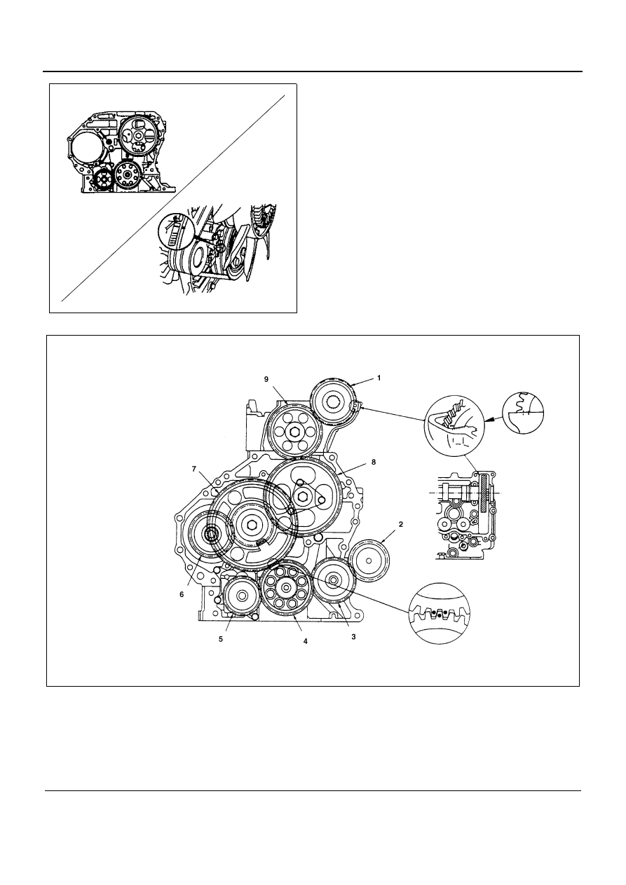
Alignment Mark Position for Each Gear

4. Flywheel Housing

1) Carefully wipe any foreign material from the cyl-

inder body rear face.

2) Apply the recommended liquid gasket (Three

Bond 1207C) or its equivalent to the shaded ar-
eas shown in the illustration.

N6A0440E

Legend

1. Camshaft gear

6. Injection pump gear

2. Power steering pump gear

7. Idle gear A

3. Power steering pump idle gear

8. Idle gear B

4. Crankshaft gear

9. Idle gear C

5. Oil pump drive

N6A0441E

ENGINE (4HF1 / 4HF1-2 / 4HE1-TC / 4HG1 / 4HG1-T) 6A3-37

3) Align the cylinder body knock pins with the fly-

wheel housing knock pin holes.

4) Tighten the flywheel housing bolts to the spec-

ified torque shown in the illustration.

Tighten:
Flywheel housing bolt to

• (A): 96 N

⋅m (9.8 kg⋅m/71 lb⋅ft)

• (B): 48 N

⋅m (4.9 kg⋅m/35 lb⋅ft)

• (C): 94 N

⋅m (9.6 kg⋅m/69 lb⋅ft)

• (D): 25 N

⋅m (2.6 kg⋅m/19 lb⋅ft)

• (E): 76 N

⋅m (7.7 kg⋅m/56 lb⋅ft)

• (F): 48 N

⋅m (4.9 kg⋅m/35 lb⋅ft)

• Tighten the bolts marked with “E” or “B” from the in-

jection pump side, and those with “F” from the cyl-
inder body side.

Tighten:
Flywheel housing bolt (G) to 96 N

⋅m (9.8 kg⋅m/71 lb⋅ft)

5. Power Steering Pump Idle Gear

1) Apply the engine oil to the idle gear shaft.
2) Install the idle gear shaft (1) with the idle gear

(2) to the cylinder body A portion as shown in
the illustration.

Tighten:
Idle gear shaft bolt to 135 N

⋅m (13.6 kg⋅m/98 lb⋅ft)

N6A0442E

N6A0181E

N6A0182E

N6A0183E

6A3-38 ENGINE (4HF1 / 4HF1-2 / 4HE1-TC / 4HG1 / 4HG1-T)

6. Power steering Pump Idle Gear Cover

Install the gear cover with the O-ring.

Tighten:
Gear cover bolt to 19 N

⋅m (1.9 kg⋅m/14 lb⋅ft)

7. Oil Pan
8. Spacer Rubber

Above works refer to “OIL PAN” section in this
manual.

9. Crankshaft Rear Slinger

10. Crankshaft Rear Oil Seal
11. Flywheel

Above works refer to “CRANKSHAFT REAR OIL
SEAL” section in this manual.

12. Injection Pump Assembly

Above works refer to “INJECTION PUMP ASSEM-
BLY” section in this manual.

13. Oil Pipe

Tighten:
Oil pipe joint bolt to 17 N

⋅m (1.7 kg⋅m/12 lb⋅ft)

14. Engine Control Lever Assembly

Tighten:
Engine control lever bolt to 24 N

⋅m (2.4 kg⋅m/17 lb⋅ft)

15. Engine Control Wire

16. Driven Plate

Use the clutch pilot aligner to install the driven
plate.
Clutch Pilot Aligner: 5-8840-2240-0

N6A0184E

N6A0185E

N6A0448E

N6A0449E

ENGINE (4HF1 / 4HF1-2 / 4HE1-TC / 4HG1 / 4HG1-T) 6A3-39

17. Clutch Pressure Plate Assembly

1) Align the clutch pressure plate with the flywheel

knock pin.

2) Tighten the pressure plate bolts to the specified

torque in numerical order.

Tighten:
Clutch pressure plate bolt to 40 N

⋅m (4.1 kg⋅m/30 lb⋅ft)

18. Cylinder Head Gasket

Above works refer to “CYLINDER HEAD GASKET”
section in this manual.

19. Cylinder Head Assembly

Above works refer to “CYLINDER HEAD GASKET”
section in this manual.

20. Camshaft Bearing Lower
21. Camshaft Assembly
22. Camshaft Bearing Upper
23. Camshaft Bearing Cap
24. Valve Cap
25. Rocker Arm Shaft Assembly

Above works refer to “CAMSHAFT ASSEMBLY”
section in this manual.

26. Head Cover Gasket
27. Cylinder Head Cover

Above works refer to “CYLINDER HEAD COVER”
section in this manual.

28. Nozzle Cover
29. Engine Assembly

Above works refer to “ENGINE ASSEMBLY” sec-
tion in this manual.

Legend

1. Clutch pilot aligner
2. Clutch pressure plate assembly
3. Driven plate

Legend

A. Knock pin

N6A0351E

N6A0352E


Content   ..  344  345  346  347   ..