Isuzu N-Series. Manual - part 310
00-52 SERVICE INFORMATION
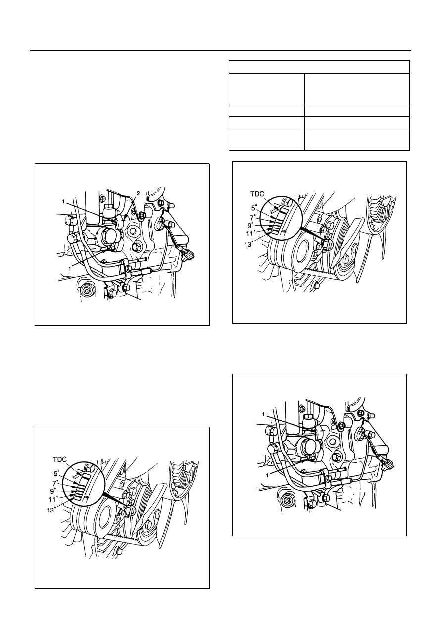
Injection Timing Adjustment
Injection Pump Notched Line Inspection
1. Check the injection pump bracket nuts (1) for
looseness.
Tighten as required.
2. Check that the notched lines (2) on the injection
pump bracket and the timing gear case are
aligned.
If the notched lines are not aligned, the injection
timing must be checked.
3. Some time, check injection timing on the crank
damper pulley.
If the injection timing aligned with in correct, the in-
jection timing must be readjusted.
Injection Timing Adjustment
1. Turn the crankshaft until the timing mark on the
crankshaft damper pulley is aligned with the BTDC
(injection timing of each engine model) mark in the
illustration.
2. Remove the two foam rubbers.
3. Loosen the four injection pump fixing nuts (1).
This will allow the pump to pivot.
Do not bend or scratch the fuel pipe.
4. Align the notched line between the injection pump
bracket and the timing gear case.
Make sure that the timing mark on the crank damp-
er pulley is aligned with correct injection timing.
N6A0050E
N6A0060E
Injection Timing
deg
4HF1
4HE1-TC
(4HE1-XS, XN)
BTDC 8
4HG1
BTDC 9
4HEI-T
BTDC 7
4HE1-TC
(4HE1-XS)
BTDC 9 (Spec EURO3)
N6A0060E
N6A0053E