Isuzu N-Series. Manual - part 250


  Index      Isuzu     Isuzu N-Series - service repair manual


Search            


Content   ..  248  249  250  251   ..


Isuzu N-Series. Manual - part 250


ANTI-LOCK BRAKE SYSTEM (ABS) 5A4-65

4. Connect speed sensor connector.

Front Speed Sensor Rotor

Components

Removal

1. Remove disc brake assembly and support the cal-

iper assembly so that the brake hose is not
stretched or damaged.

2. Remove hub cap.
3. Remove cotter pin and hub nut.
4. Remove washer.
5. Remove hub and disc assembly.
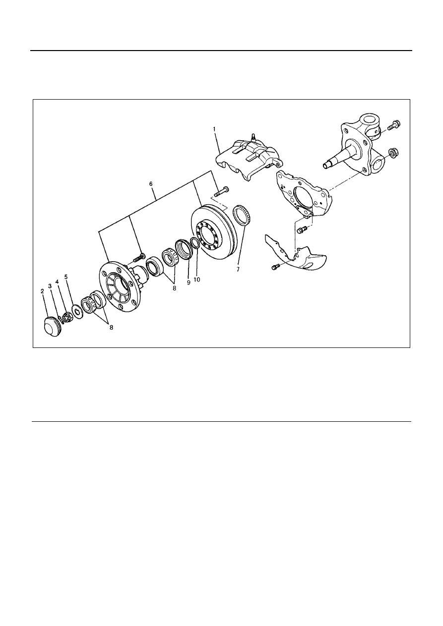
Legend

1. Disc Brake Assembly

6. Hub and Disc Assembly

2. Hub Cap

7. Speed Sensor Rotor

3. Cotter Pin

8. Inner Bearing and Outer Bearing

4. Hub Nut

9. Oil Seal

5. Washer

10. Spacer

N5A1052E

5A4-66 ANTI-LOCK BRAKE SYSTEM (ABS)

6. Remove speed sensor rotor.
7. Remove inner bearing, oil seal spacer.

Inspection and Repair

1. Check the speed sensor rotor for damage including

tooth chipping, and if damaged, replace the speed
sensor rotor.

Installation

1. Using a bench press, install speed sensor rotor.
2. Install spacer onto the knuckle spindle.
3. Apply grease into the outer and inner bearings and

install bearings in the hub.

4. Install oil seal into hub and disc assembly and in-

stall hub and disc assembly on to the knuckle spin-
dle.

Preload Adjustment

Adjust the wheel bearing as follows:

1. Tighten the nut until you are unable to manually ro-

tate the hub and disc assembly.

2. Loosen the nut.
3. Attach a spring balancer to one stud. Gradually re-

tighten the nut until the hub and disc assembly
bearing is adjusted to the specified preload.

• Hub bearing preload

New Hub Bearing: 9.8 — 24.5 N (1 — 2.5 kg/
2.2 — 5.5 lb)
Reused Hub Bearing: 4.9 — 19.6 N (0.5 — 2
kg/1.1 — 4.4 lb)

4. Install a cotter pin through the nut and knuckle and

bend it over.

• If the notch in the nut does not line up with the

cotter pin hole in the knuckle, tighten the nut
until it does. Do not loosen the nut to line up a
notch and the knuckle hole.

5. Apply grease into the hub cap and install it.

• 0.4 N (40 g/0.09 lb)

6. Install the disc brake assembly and tighten two

bolts to the specified torque.

Tighten:
Bolts to 221 N

⋅m (22.5 kg⋅m/163 lb⋅ft)

N5A1053E

N5A1054E

ANTI-LOCK BRAKE SYSTEM (ABS) 5A4-67

Rear Speed Sensor

Components

Legend

1. Brake Drum

3. Speed Sensor

2. Speed Sensor Fixing Bolt

4. Speed Sensor Bracket

N5A1055E

5A4-68 ANTI-LOCK BRAKE SYSTEM (ABS)

Removal

1. Disconnect speed sensor connector.
2. Remove brake drum.
3. Remove speed sensor fixing bolt.
4. Remove speed sensor.
5. Remove speed sensor bracket.

Inspection and Repair

1. Check the speed sensor for presence of foreign

materials; remove any dirt, etc.

2. Check the speed sensor for damage, and replace

the speed sensor if necessary.

3. Check the speed sensor harness for a short or an

open, and replace with a new one if necessary. To
check for harness short or open, bend or stretch
the cable while checking for continuity.

Installation

1. Install speed sensor bracket and tighten the nut to

the specified torque.

Tighten:
Nut to
GVW Range 12,000 lbs. and 14,500 lbs. model:
108 N

⋅m (11 kg⋅m/80 lb⋅ft)

GVW Range 17,950 lbs. model:
157 N

⋅m (16 kg⋅m/116 lb⋅ft)

2. Install the speed sensor and take care not to hit the

speed sensor during installation.

3. Install the speed sensor fixing bolt and tighten it to

the specified torque.

Tighten:
Bolt to 18 N

⋅m (1.8 kg⋅m/13 lb⋅ft)

4. Install brake drum and tighten bolts to the specified

torque.

Tighten:
Bolts to 13 N

⋅m (1.3 kg⋅m/9.5 lb⋅ft)

5. Connect speed sensor connector.

Notice:
Confirm that the harness is not twisted when connecting
the speed sensor connector.

Legend

1. Speed Sensor Connector
2. Front
3. Speed Sensor
4. Rear Axle

N5A1056E


Content   ..  248  249  250  251   ..