Isuzu N-Series. Manual - part 238
ANTI-LOCK BRAKE SYSTEM (ABS) 5A4-17
ABS Relay
Test condition: Engine stops with the key turned to the
“ON” position. To be more specific, the test is conducted
with the brake pedal stepped on after stepping once and
releasing.
Make sure of the working sound of the ABS relay.
The circuit is normal if the working sound of the ABS re-
lay is made in accordance with Tech 2’s instruction.
ABS Motor
Test condition: Engine stops with the key turned to the
“ON” position. To be more specific, the test is conducted
with the brake pedal stepped on after stepping once and
releasing.
Make sure of the working sound of the ABS motor.
The circuit is normal if the working sound of the ABS mo-
tor is made in accordance with Tech 2’s instruction.
Exhaust Brake Cut Relay
Test condition: Engine stops with the key turned to the
“ON” position. To be more specific, the test is conducted
with the brake pedal stepped on after stepping once and
releasing.
Make sure of the working sound of the exhaust brake cut
relay.
The circuit is normal if the working sound of the exhaust
brake cut relay is made in accordance with Tech 2’s in-
struction.
Hold Valve Test
Purpose: The purpose of this test is to detect brake pipe
and valve line harness wire wrong connections and
valve trouble.
This test will help you confirm the result of your repair
service including the removal/reinstallation of brake
pipe, valve line harness and valve.
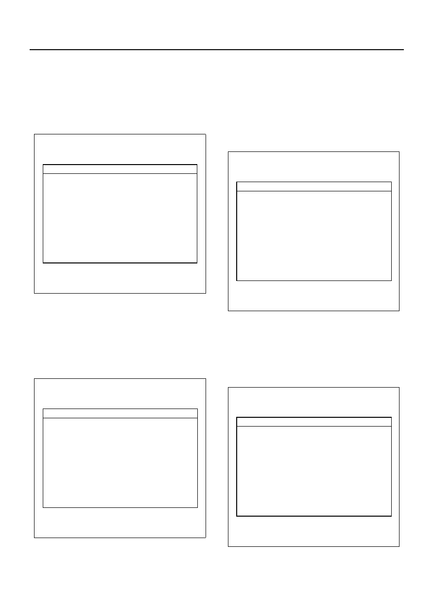
Actuator Test
F1:
F2:
F3:
Return Pump Relay Test
Front Left Solenoid Valve Test
Front Right Solenoid Valve Test
F4:
F5:
F6:
F7:
Rear Left Solenoid Valve Test
Rear Right Solenoid Valve Test
ABS Check Light Test
Exhaust Brake Cut Test
N5A1020E
Actuator Test
F0:
F2:
F3:
ABS Relay Test
Front Left Solenoid Valve Test
Front Right Solenoid Valve Test
Rear Left Solenoid Valve Test
Rear Right Solenoid Valve Test
ABS Check Light Test
Exhaust Brake Cut Test
F4:
F5:
F6:
F7:
N5A1021E
Actuator Test
F0:
F1:
F2:
F3:
ABS Relay Test
Return Pump Relay Test
Front Left Solenoid Valve Test
Front Right Solenoid Valve Test
Rear Left Solenoid Valve Test
Rear Right Solenoid Valve Test
ABS Check Light Test
F4:
F5:
F6:
N5A1022E
Actuator Test
F0:
F1:
F3:
ABS Relay Test
Return Pump Relay Test
Front Right Solenoid Valve Test
Rear Left Solenoid Valve Test
Rear Right Solenoid Valve Test
ABS Check Light Test
Exhaust Brake Cut Test
F4:
F5:
F6:
F7:
N5A1023E