Isuzu N-Series. Manual - part 237


  Index      Isuzu     Isuzu N-Series - service repair manual


Search            


Content   ..  235  236  237  238   ..


Isuzu N-Series. Manual - part 237


ANTI-LOCK BRAKE SYSTEM (ABS) 5A4-13

YES: Clear vehicle type and reread vehicle harness in-
formation.
NO: Return

DTC Status

Current Diagnostic Trouble Codes
This selection will display all DTCs that have failed dur-
ing the present ignition cycle.
History Diagnostic Trouble Codes
This selection will display only DTCs that are stored in
the EHCU’s history memory.

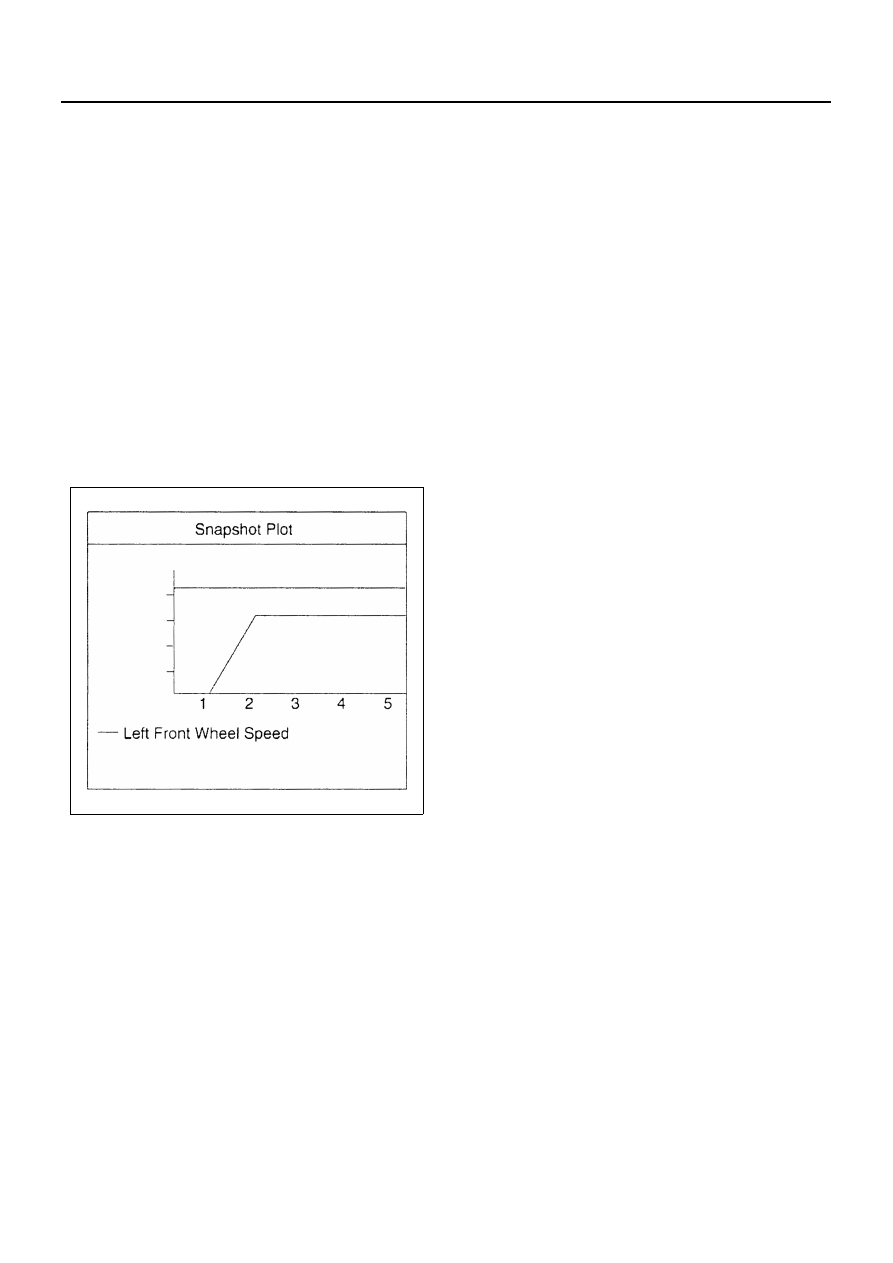
Plotting Snapshot Graph

This test selects several necessary items from the data
list to plot graphs and makes data comparison on a long
term basis. This test can check ABS performance and
defect by graphing wheel speed differences between
right and left sides, and front and rear sides obtained
from the ABS data list menu.

For trouble diagnosis, you can collect graphic data
(snap shot) directly from the vehicle.
You can replay the snapshot data as needed.
Therefore, accurate diagnosis is possible, even though
the vehicle is not available.

N5A1014E

5A4-14 ANTI-LOCK BRAKE SYSTEM (ABS)

Plotting Graph Flow Chart (Plotting Graph after Obtaining Vehicle Information)

N5A1015E

ANTI-LOCK BRAKE SYSTEM (ABS) 5A4-15

Flow Chart for Snapshot Replay (Plotting Graph)

N5A1016E

5A4-16 ANTI-LOCK BRAKE SYSTEM (ABS)

Tech 2 Data Display

Use the Tech 2 data Values only after the ABS Diagnos-
tic System Check has been completed, no DTC(s) were
noted, and you have determined that the on-board diag-
nostics are functioning properly. Tech 2 values from a
properly-running engine may be used for comparison
with the engine you are diagnosing.
ABS Data
Ignition SW is “ON” position.
(For example)

Special Function

There are 12 different menus available for this test.
The state of each circuit can be tested by using these
menus. Especially when DTC cannot be detected, a
faulty circuit can be diagnosed by testing each circuit by
means of these menus.
Even when DTC has been detected, the circuit tests us-
ing these menus could help discriminate between a me-
chanical trouble and an electrical trouble.

In all cases test condition; Engine stops with the key
turned to the “ON” position. To be more specific, the test
is conducted with the brake pedal stepped on after step-
ping once and releasing.

• Engine: Stop
• Ignition SW: ON
• Brake Pedal: ON-OFF-ON

If the Ignition SW was turned OFF or communication
was lost, make sure to apply the brake pedal ON-OF-
FON once again and then continue the test.

ABS Warning Lamp

Test condition: Engine stops with the key turned to the
“ON” position. To be more specific, the test is conducted
with the brake pedal stepped on after stepping once and
releasing.

• The circuit is normal if the warning light in the meter

panel comes on and goes out in accordance with
Tech 2’s instruction.

N5A1017E

Actuator Test

F0:
F1:
F2:
F3:

ABS Relay Test
Return Pump Relay Test
Front Left Solenoid Valve Test
Front Right Solenoid Valve Test
Rear Left Solenoid Valve Test
Rear Right Solenoid Valve Test
ABS Check Light Test
Exhaust Brake Cut Test

F4:
F5:
F6:
F7:

N5A1018E

Actuator Test

F0:
F1:
F2:
F3:

ABS Relay Test
Return Pump Relay Test
Front Left Solenoid Valve Test
Front Right Solenoid Valve Test
Rear Left Solenoid Valve Test
Rear Right Solenoid Valve Test

Exhaust Brake Cut Test

F4:
F5:

F7:

N5A1019E


Content   ..  235  236  237  238   ..