Isuzu N-Series. Manual - part 231


  Index      Isuzu     Isuzu N-Series - service repair manual


Search            


Content   ..  229  230  231  232   ..


Isuzu N-Series. Manual - part 231


HYDRAULIC BRAKES 5A-83

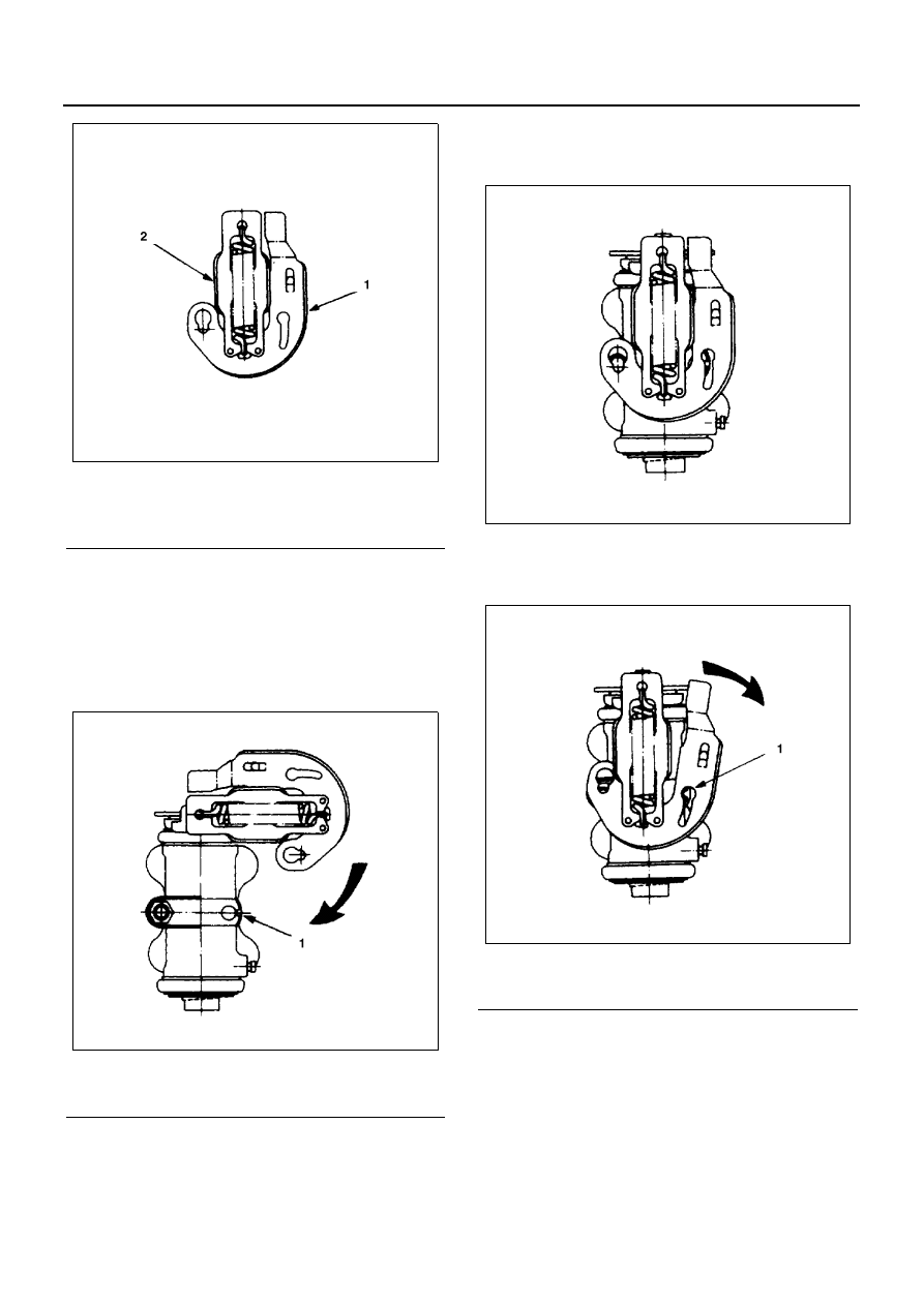
1) Hook one end of the overtravel spring to the ad-

juster lever hole as shown in the illustration.

2) Hook the other end of the overtravel spring to

the fitting slot.

3) Turn the overtravel spring 90 degrees counter-

clockwise as shown in the illustrations.

(Wheel Cylinder Body)

Install the adjuster lever and the overtravel spring to the
wheel cylinder body.

1) Hook the overtravel spring fitting slot side to the

wheel cylinder body bracket hole.

2) Turn the adjuster lever and the overtravel

spring 90 degrees clockwise as shown in the il-
lustration.

3) Turn the adjuster lever slightly clockwise to at-

tach the adjuster lever hole to the wheel cylin-
der body hook.

4) Push the wheel cylinder body and bracket to

the left as shown in the illustration.

Legend

1. Adjuster lever
2. Overtravel spring

Legend

1. Wheel cylinder

N5A0257E

N5A0258E

Legend

1. Cylinder body hook

N5A0259E

N5A0260E

5A-84 HYDRAULIC BRAKES

5) Turn the adjuster lever counterclockwise to in-

stall the pin head through the adjuster lever
hole.

10. Return Spring

Hook the return spring to the wheel cylinder body
pin.

Drum Inside Diameter 300, 320 mm

1. Reassemble the spring hook (short) to the bracket

square hole and spring hook (long) to the lever.

2. Turn the lever to the direction at the connecting

point of lever and spring and reassemble the lever
to the bracket.

Legend

1. Pin head

Legend

1. Return spring

N5A0261E

N5A0262E

Legend

1. Lever
2. Bolt sleeve
3. Bracket
4. Spring hook (short): Hook to the bracket 

square hole

5. Lever fixing bolt 

Torque: 7.85 — 11.77 N

⋅m (0.80 — 1.20 kg⋅m/

5.79 — 8.68 lb

⋅ft)

6. Body surface
7. Spring hook (Long): Hook the lever

N5A0263E

N5A0264E

HYDRAULIC BRAKES 5A-85

3. Install the lever fixing bolt to the specified torque.
4. Make sure not to bite the lever between the bolt

sleeve and body surface.

5. Make sure fit the lever to the gear properly after fix-

ing the bolt.

Plain washer
Make sure to assemble the plain washer of coating side
to the adjust side.

Assemble the plain washer with the copper-colored sur-
face facing inward and the coating (black) surface facing
outward.

Notice:
Failure to assemble the plain washer or assembling it in-
side out causes auto adjuster not to operate properly.
Be sure to assemble it correctly.

Drum Inside Diameter 370 mm

1. Assemble the piston.

1) Apply grease to the outer circumference of pis-

ton (1) and installation groove of boot. Install
the boot (2) and apply grease to the insertion
groove of cup.

Notice:
After installation of boot, make sure that there are still
enough grease in boot.

2) Assemble the grease-applied piston cup (3) to

piston.

Grease: NIGLUBE RX-2

2. Install the washer (OIL LESS) (1).

Apply grease to both sides.

Plain washer
Make sure to assemble the plain washer of coating side
to the adjust side.

Assemble the plain washer with the copper-colored sur-
face facing inward and the coating (black) surface facing
outward.

Notice:
Failure to assemble the plain washer or assembling it in-
side out causes auto adjuster not to operate properly.
Be sure to assemble it correctly.

3. Install the washer (SUS) (2).
4. Install the adjuster gear and nut assembly (3).

Apply grease to the inner surface of piston and ad-
juster gear and nut assembly, and assemble it to
piston.

Grease: NIGLUBE RX-2

Legend

1. Turn the lever to the arrow, and extend the 

spring

2. Assemble the lever from the direction
3. Connecting point of lever and spring

N5A0265E

3

2

Apply grease

Apply grease

1

N5A0454E

N5A0265E

5A-86 HYDRAULIC BRAKES

5. Install the adjusting screw (4).

Apply grease and screw it in to adjuster gear and
nut assembly.

6. Install the cylinder assembly.

Apply grease to the sliding part of piston. Assemble
the piston and install the boot.

Grease: NIGLUBE RX-2

7. Assemble the lever assembly.

Install the pin (2), spring assembly (3), washer (4),
wave washer (5) and snap ring (6) to lever (1).

8. Fix the cylinder assembly in a vise and assemble

the tip of spring assembly to cutout groove of pis-
ton flange.

9. While matching the lever to cylinder's hook (3) and

stretching the spring assembly, fix the lever to cyl-
inder pin (2) through the double hole (1) of lever.

1

2

3

4

Apply grease

N5A0455E

1

2

3

4

5

6

N5A0456E

N5A0457E

1

2

3

N5A0458E


Content   ..  229  230  231  232   ..