Isuzu N-Series. Manual - part 225


  Index      Isuzu     Isuzu N-Series - service repair manual


Search            


Content   ..  223  224  225  226   ..


Isuzu N-Series. Manual - part 225


HYDRAULIC BRAKES 5A-59

2. ATF Pipe

• Install ATF pipes to hydraulic booster.

3. Brake Pipe and Hose

• Install master cylinder hydraulic lines to master

cylinder.

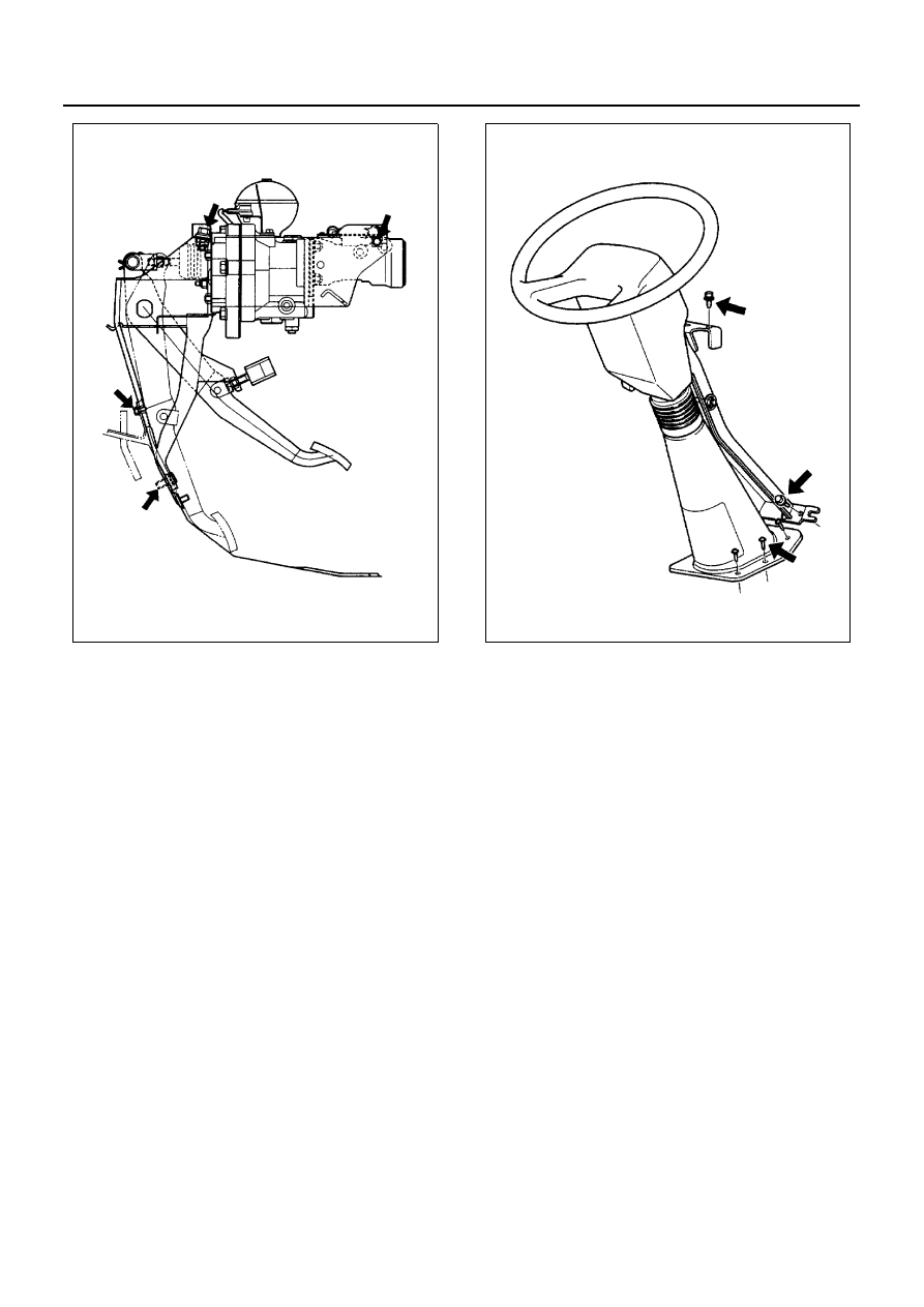
4. Steering Wheel and Column Assembly

• Set steering wheel and column assembly.
• Install mounting bolts, nuts and screws to body.
• Install key bolt and nut.

Tighten:
Key bolt to 38 N

⋅m (3.9 kg⋅m / 28 lb⋅ft)

• Install inspection window.

5. Heat Protector

• Install hydraulic booster heat protector.

6. Instrument Panel and Duct

• Install ventilation duct and instrument panel as-

sembly.

7. Meter

• Install meter assembly and harness connector.

8. Meter CIuster

• Install meter cluster.

9. Battery ground cable.

10. After attaching it to the vehicle, always replenish

with new hydraulic oil (Besco ATF Ill), and com-
pletely release the air from the hydro boost.

11. Bleed brake lines.
12. Release the parking brake and remove the wheel

blocks.

N5A0208E

N5A0207E

5A-60 HYDRAULIC BRAKES

Hydraulic Booster

Legend

1. Clevis pin

4. Master cylinder

2. Hydraulic booster nut

5. Hydraulic booster

3. Master cylinder nut

N5A0212E

HYDRAULIC BRAKES 5A-61

Removal

1. Clevis Pin
2. Hydraulic Booster Nut

• Four hydraulic booster mounting nuts at pedal

bracket.

• Remove master cylinder with hydraulic boost-

er.

3. Mastcr Cylinder Nut

• Four nuts retaining master cylinder to hydraulic

booster.

4. Master Cylinder
5. Hydraulic Booster

Installation

1. Hydraulic Booster
2. Master Cylinder Assembly
3. Master Cylinder Nut

Tighten:
Master cylinder nut to 14 N

⋅m (1.4 kg⋅m / 122 lb⋅in)

4. Hydraulic Booster Nut

• Four hydraulic booster mounting nuts to pedal

bracket.

Tighten:
Hydraulic booster nut to 14 N

⋅m (1.4 kg⋅m / 122 lb⋅in)

5. Clevis Pin

• Connect hydraulic booster clevis to brake pedal

and install clevis pin.

N5A0213E

5A-62 HYDRAULIC BRAKES

Accumulator and O-ring Replacement

Removal

• BIock the vehicle and apply the parking brake.
• Disconnect the battery ground cable.
• Reduce the pressure of the hydraulic oil in the ac-

cumulator by brake pedal operation with the engine
off, and after confirming that the temperature of the
hydro boost assembly has been reduced, remove
the hydro boost assembly from the vehicle.
1) Remove meter cluster.
2) Remove meter assembly and harness connec-

tor.

3) Remove ventilation duct.
4) Using an oil filter wrench, remove accumulator

and O-ring.

Installation

1. Verify that there is no foreign matter adhering to

the screw part of the accumulator or to the attach-
ment part on the booster side.

2. Put an O-ring coated with new hydraulic oil (ATF

DEXRON

®

-III) into the screw part of the accumula-

tor, being careful not to damage it.
Always use a new O-ring.

3. Using an oil filter wrench, hold the accumulator

shell fixed, and tighten it via the wrench to the
specified torque.

Tighten:
Accumulator to 29 N

⋅m (3.0 kg⋅m / 22 lb⋅ft)

4. Install ventilation duct.
5. Connect harness connector and install meter as-

sembly.

6. Install meter cluster.
7. Connect the battery ground cable.
8. After attaching it to the vehicle, always replenish

with new hydraulic oil (ATF DEXRON

®

-III), and

completely release the air from the hydro boost.

9. Release the parking brake and remove the wheel

blocks.

Notice:
How to dispose of the accumulator
To dispose of the accumulator, drill a hole in the position
shown in the diagram according to the indications print-
ed on the accumulator, completely release the nitrogen
gas scaled inside the accumulator, then dispose of the
accumulator.
Concerning disposal with the hydro boost assembly as
well, dispose of it after first letting out all the nitrogen gas
inside the accumulator, by the above method.

Legend

1. Accumulator
2. Stud bolt
3. Cover boss
4. Lock nut
5. Clevis
6. Operating rod
7. Guard
8. Flange

N5A0010E

Legend

1. Accumulator
2. HEX25
3. Thread
4. O-ring
5. Drilling point for gas releasing

N5A0216E


Content   ..  223  224  225  226   ..