Isuzu N-Series. Manual - part 223


  Index      Isuzu     Isuzu N-Series - service repair manual


Search            


Content   ..  221  222  223  224   ..


Isuzu N-Series. Manual - part 223


HYDRAULIC BRAKES 5A-51

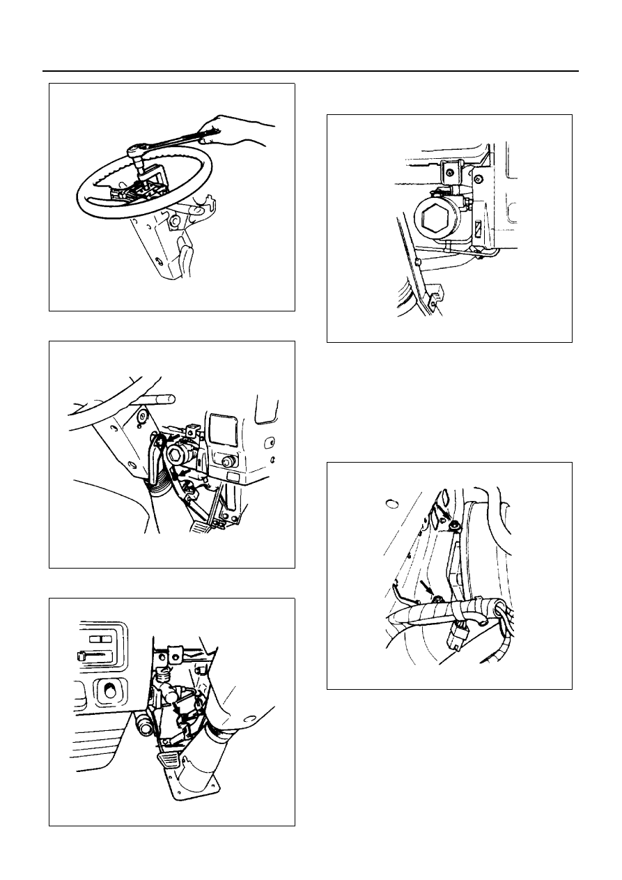
Remove the tilt lever and steering cowl.

Disconnect the wire harness connectors.

8. Vacuum Booster and Brake Pedal Assembly

1) Disconnect the brake pipes and hoses.

2) Plug or cover the brake rubber hoses, pipes

and the master cylinder brake fluid ports to pre-
vent brake fluid spillage.
If brake fluid spillage occurs, wipe it up immedi-
ately.

3) Remove the brake pedal bracket fixing bolts

and vacuum booster and brake pedal assem-
bly.

N5A0182E

N5A0183E

N5A0184E

N5A0185E

N5A0186E

5A-52 HYDRAULIC BRAKES

4) Remove the brake pedal and master cylinder.

5) Remove the vacuum booster assembly from

brake pedal assembly.

Installation

1. Vacuum Booster and Brake Pedal Assembly

1) Vacuum booster cannot be overhauled. If it is

found faulty, replace its assembly with a new
one.

2) Make necessary adjustment, so that distance

between end of push rod and flange face is ad-
justed to 18.2 mm (0.717 in) in condition of vac-
uum applying.

3) Push rod length (A) is measured from the cen-

ter of the clevis pin hole to the mounting surface
of the brake pedal bracket. Adjusted to 109 mm
(4.291 in); without spacer, 129 mm (5.079 in);
with spacer and tighten the lock nut. When
fixed under this condition, there is no need to
adjust the height of brake pedal from floor and
free play.

N5A0187E

N5A0188E

N5A0189E

N5A0005E

HYDRAULIC BRAKES 5A-53

4) Install the vacuum booster to brake pedal as-

sembly.

• Adjust the clearance between the tip of thread-

ed portion of the stop light switch and the pedal
arm to 0.5 — 1.0 mm (0.02 — 0.04 in).

5) Tighten the vacuum booster bolts to the speci-

fied torque. 

Tighten:
Vacuum booster bolts to 14 N

⋅m (1.4 kg⋅m / 122 lb⋅in)

6) Install the master cylinder assembly to vacuum

booster or brake pedal assembly.

7) Tighten the master cylinder nut to the specified

torque.

Tighten:
Master cylinder nut to 14 N

⋅m (1.4 kg⋅m / 122 lb⋅in)

8) Install the vacuum booster and brake pedal as-

sembly.

Tighten:
Vacuum booster and brake pedal assembly bolts to 42
N

⋅m (4.3 kg⋅m / 32 lb⋅ft)

9) Connect the brake hoses and pipes.

N5A0006E

N5A0189E

N5A0195E

N5A0186E

5A-54 HYDRAULIC BRAKES

2. Steering Cowl Assembly

1) Connect the wire harness connectors.
2) Install the steering cowl.

Tighten:
Steering cowl bolt to 14 N

⋅m (1.4 kg⋅m / 122 lb⋅in)

3) Install the tilt lever.

Tighten:
Tilt lever bolt to 45 N

⋅m (4.6 kg⋅m / 33 lb⋅ft)

4) Install the steering wheel.

Tighten:
Steering wheel nut to 49 N

⋅m (5.0 kg⋅m / 36 lb⋅ft)

3. Windshield Washer Tank
4. Brake and Clutch Fluid Reservoir
5. Center Duct (NPR model only)
6. Defroster Nozzle and Vent Duct
7. Stay
8. Instrument Panel

For the installation procedure for above, refer to
Section 2 CAB AND FRAME.

N5A0185E

N5A0183E

N5A0199E


Content   ..  221  222  223  224   ..