Isuzu N-Series. Manual - part 221


  Index      Isuzu     Isuzu N-Series - service repair manual


Search            


Content   ..  219  220  221  222   ..


Isuzu N-Series. Manual - part 221


HYDRAULIC BRAKES 5A-43

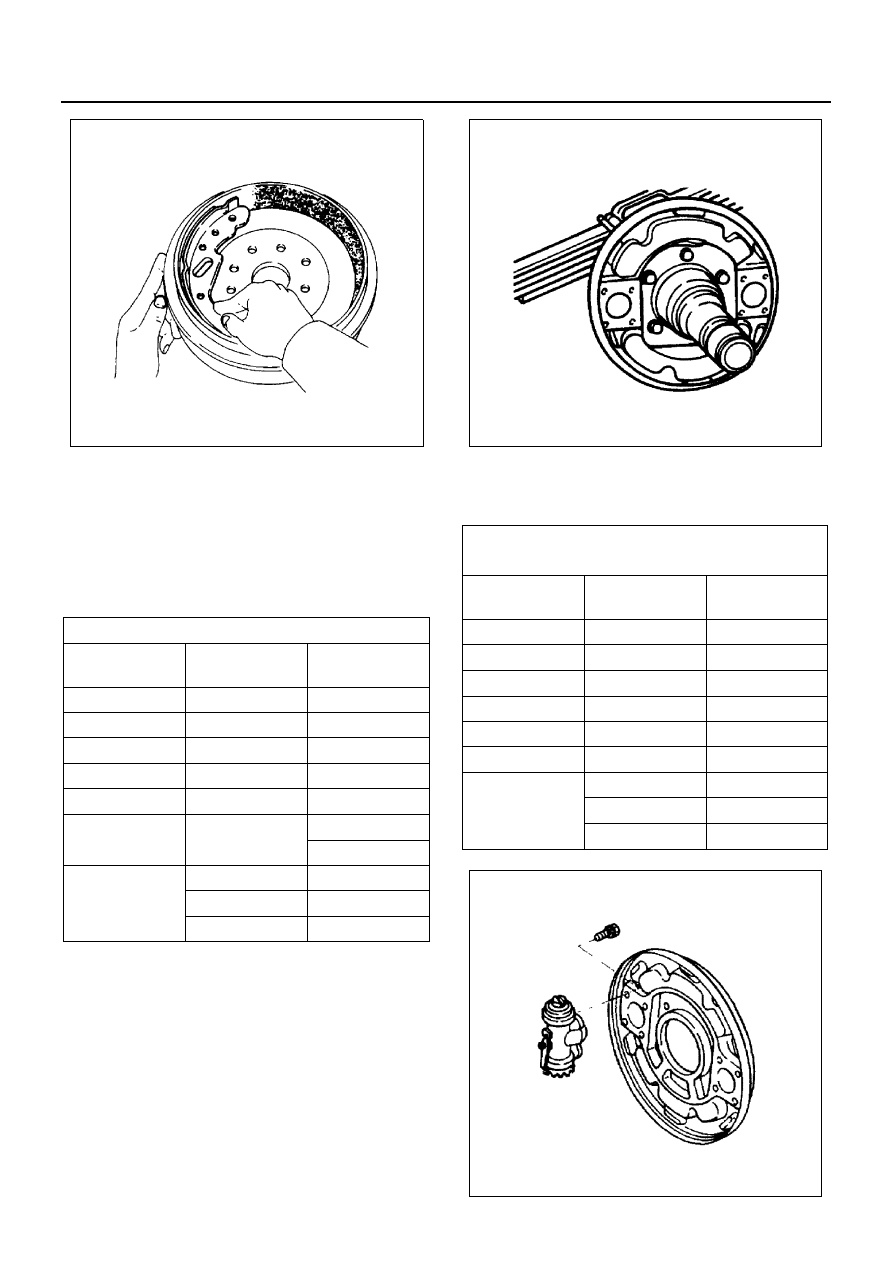
4. Correct any areas having poor contact with sand-

paper.

5. Repeat Steps 1 through 4 until the contact between

the brake lining and the brake drum is perfect.

Installation

1. Back Plate

Tighten the back plate bolts to the specified torque.

* Single Tire models
** Dual Tire models

2. Wheel Cylinder Assembly

Tighten the wheel cylinder assembly bolts to the
specified torque.

Back Plate Bolt Torque

N

⋅m (kg⋅m/lb⋅ft)

Drum Inside 
Dia. mm (in)

Lining

Width mm (in)

228.6 (9.00)

75 (2.95)

108 (11.0/80)

240.0 (9.45)

60 (2.36)

108 (11.0/80)

260.0 (10.24)

90 (3.54)

108 (11.0/80)

279.4 (11.00)

60 (2.36)

74 (7.5/54)

290.0 (11.42)

75 (2.95)

108 (11.0/80)

300.0 (11.81)

75 (2.95)

* 44 (4.5/33)

** 108 (11.0/80)

320.0 (12.60)

75 (2.95)

108 (11.0/80)

100 (3.94)

108 (11.0/80)

120 (4.72)

157 (16.0/116)

N5A0142E

Wheel Cylinder Assembly Bolt Torque 

N

⋅m (kg⋅m/lb⋅ft)

Drum Inside 

Dia. mm (in)

Lining

Width mm (in)

228.6 (9.00)

75 (2.95)

34 (3.5/25)

240.0 (9.45)

60 (2.36)

25 (2.5/18)

260.0 (10.24)

90 (3.54)

43 (4.4/32)

279.4 (11.00)

60 (2.36)

27 (2.8/20)

290.0 (11.42)

75 (2.95)

25 (2.5/18)

300.0 (11.81)

75 (2.95)

34 (3.5/25)

320.0 (12.60)

75 (2.95)

43 (4.4/32)

100 (3.94)

74 (7.5/55)

120 (4.72)

94 (9.6/69)

N5A0173E

N5A0146E

5A-44 HYDRAULIC BRAKES

3. Brake Pipe

Tighten the brake pipe flare nuts to the specified
torque.

Tighten:
Brake pipe flare nuts to 16 N

⋅m (1.6 kg⋅m / 12 lb⋅ft)

Notice:
Take care not to twist the piping.

4. Brake Shoe and Return Spring

1) Before setting the brake shoes, apply a thin

coat of molybdenum disulfide grease to the
back plate portions (1) contacting the brake
shoe edge as shown in the illustrations.

2) Apply a coat of molybdenum disulfide grease to

the wheel cylinder parts contacting the brake
shoe (2).

3) Set the brake shoe assembly to the cylinder ad-

justing screw at the brake shoe small angle
end.
Do not install it at the round end.

4) Install the brake shoes and the return springs to

the wheel cylinders.
Keep the brake lining clean.

5. Shoe Holding Spring, Cup and Pin

1) Before installing the holding pin.

Apply a coat of molybdenum disulfide grease to
the holding cup seating faces (1) contacting the
brake shoe.

2) After installation of the pins, cups and the

springs, make sure the pin (2) seats to the cup
(3) properly.

6. After installation of brake drum, be sure to perform

the preload adjustment of hub bearing.

7. Bleed the air from brake.

With Auto-adjuster
For the drum brake with auto-adjuster, perform the fol-
lowing procedure before Step 6 and 7.

1. Measure the internal diameter of the brake drum.

• Take measurement of the distance at (A), (B)

and (C) points.

N5A0147E

N5A0150E

N5A0151E

N5A0152E

HYDRAULIC BRAKES 5A-45

2. Measure the external diameter of the brake shoe.

• Take measurement of the distance at (A), (B)

and (C) points.

3. Turn the adjuster gear so that the difference be-

tween the internal diameter of the brake drum and
the internal diameter of the brake shoe becomes
0.6 mm (0.024 in).

4. Install the brake drum.

Adjustment

Without Auto-adjuster
Turn the adjuster until the brake drum stops rotating.
Depress the brake pedal several times and turn the ad-
juster furthermore. When the brake drum stops rotating
completely, turn the adjuster back for 5 to 6 notches.
With Auto-adjuster
Strongly depress the brake pedal several times while ro-
tating the brake drum in the direction of moving forward
or driving the vehicle forward. This adjusts the brake
drum clearance automatically.

N5A0003E

N5A0004E

5A-46 HYDRAULIC BRAKES

Rear Drum Brake Assembly (Drum Inside Diameter 370 mm)

Removal

• Block vehicle wheels and apply the parking brake.
• Raise the axle to clear the tire from the ground. Po-

sition jack stands under vehicle.

1. Wheel and tire assembly and brake drum and hub

assembly.

• Refer to Section 3E WHEELS AND TIRES.
• Refer to Section 4C FRONT AXLE and Section

3C FRONT SUSPENSION.

• Refer to Section 4B REAR AXLE.

2. Holder nuts.
3. Shoe return springs using a return spring plier.

Return spring plier: 9-8522-0026-0

4. Shoe and lining assemblies.
5. Brake pipes.

Notice:
The brake pipes to the wheel cylinders must be removed
before the wheel cylinders can be removed.

6. Brake hose.
7. Back plate.
8. Wheel cylinders.

Legend

1. Cotter pin

5. Wheel cylinder assembly

2. Shoe hold nut

6. Back plate

3. Brake shoe return spring

7. Brake pipe

4. Brake shoe assembly

7

1

2

3

3

4

5

6

N5A0464E


Content   ..  219  220  221  222   ..