Isuzu N-Series. Manual - part 220


  Index      Isuzu     Isuzu N-Series - service repair manual


Search            


Content   ..  218  219  220  221   ..


Isuzu N-Series. Manual - part 220


HYDRAULIC BRAKES 5A-39

Drum Inside Diameter 260 mm

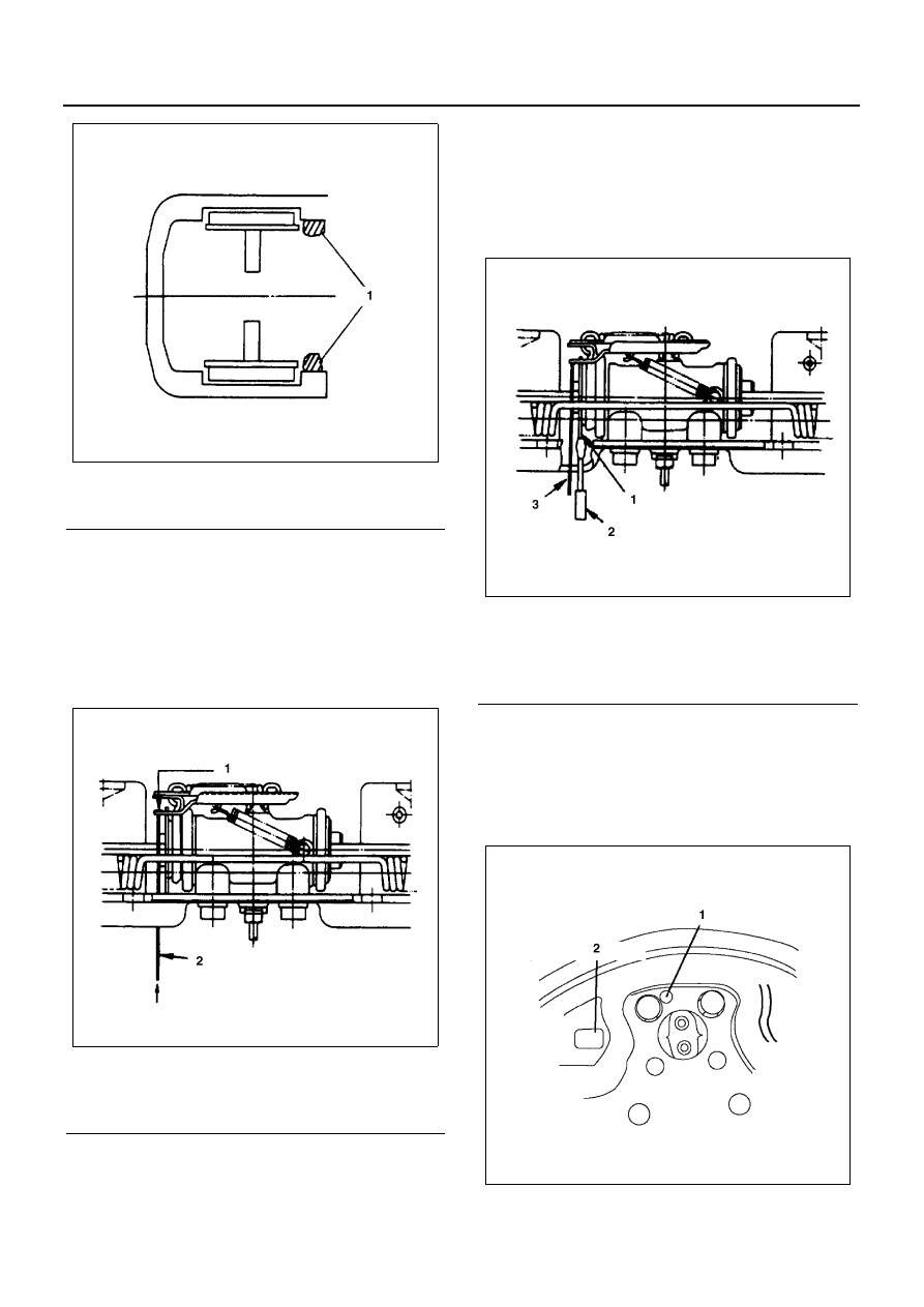
1. Remove the rubber covers from the brake lining

clearance adjusting hole and auto-adjuster lever
release hole.

2. Push up the auto-adjuster lever with a long drift or

a suitable rod.
(Outside diameter: 4 mm (0.15 in) length: 80 mm
(3.1 in))

3. Hold the auto-adjuster lever stationary.

Use a screwdriver to rotate adjusters at back of the
brake to provide clearance between lining and
drum.

Notice:
Be sure to push up the auto-adjuster lever (Step 2).
Failure to do so will result in damage to the teeth of the
auto-adjuster lever.
Take care not to damage the rubber boot with the bar or
the screwdriver.

Drum Inside Diameter 320 mm

1. Remove the rubber cover from the brake lining

clearance adjusting hole and auto-adjuster lever
release hole.

2. Remove the adjust hole cover and adjuster lever

release hole cover.

Legend

1. Corroded portion

Legend

1. Auto-adjuster lever
2. Rod

N5A0128E

N5A0155E

Legend

1. Adjuster
2. Screw driver
3. Rod

N5A0156E

N5A0129E

5A-40 HYDRAULIC BRAKES

3. Using 

φ5 mm Phillips screwdriver put it into the ad-

juster lever release hole and then push up the ad-
juster lever.

4. Put the flathead screwdriver into the adjuster hole

while push up the adjuster lever.

5. Turn the adjuster gear to the marked arrow

“LOOSE” on the backing plate.

Drum Inside Diameter 240 mm

1. Remove the rubber cover from the brake lining

clearance adjusting hole/auto-adjuster lever re-
lease hole in the back plate.

2.  Insert a thin, suitable rod in the hole, and push up

the auto-adjuster lever (4).

3. With the auto-adjuster lever (4) pushed up, insert a

keystone tip screwdriver in the adjusting hole, and
turn the adjuster gear (1) to increase the gap be-
tween the gear and the brake shoe (the outside di-
ameter of the shoe will decrease).

Legend

1. Adjuster lever release hole cover
2. Adjuster hole cover

Legend

1. Adjuster lever release hole

N5A0130E

N5A0131E

Legend

1. Adjuster gear

N5A0132E

N5A0133E

HYDRAULIC BRAKES 5A-41

Notice:
Do not fail to push up the auto-adjuster lever before turn-
ing the gear. Failure to do so will result in damage to the
teeth of the gear because it is locked with the lever.
Exercise care not to damage the boot of the wheel cyl-
inder and other parts when turning the gear and pushing
up the lever.

Drum Inside Diameter 290 mm

1. Remove the rubber cover from the brake lining

clearance adjusting hole/auto-adjuster lever re-
lease hole in the back plate.

2. Insert a thin, suitable rod in the auto-adjuster lever

release hole, and push the end of the auto-adjuster
lever (3) in the direction of the arrow (4).

3. With the auto-adjuster lever (3) pushed up, insert a

keystone tip screwdriver in the adjusting hole, and
turn the adjuster gear (6) to increase the gap be-
tween the gear and the brake shoe (the outside di-
ameter of the shoe will decrease).

Notice:
Do not fail to push up the auto-adjuster lever before turn-
ing the gear. Failure to do so will result in damage to the
teeth of the gear because it is locked with the lever.
Exercise care not to damage the boot of the wheel cyl-
inder and other parts when turning the gear and pushing
up the lever.

Inspection and Repair

Make the necessary adjustments, repairs, and part re-
placements if excessive wear or damage is discovered
during inspection.
Brake Drum Inside Diameter
Visually inspect the brake drum for excessive wear and
scoring.
If the brake drum is scored or worn, lathed to the speci-
fied limit.
Use a vernier caliper to measure the brake drum inside
diameter.

Legend

1. Adjuster gear
2. Brake shoe
3. Plug hole
4. Auto-adjuster lever
5. Loosening direction

N5A0165E

Legend

1. Plug hole
2. Rotating direction of tire (forward)
3. Auto-adjuster lever
4. Loosening direction
5. Plug hole
6. Adjuster gear

Brake Drum Inside Diameter

mm (in)

Drum size

Standard

Limit

228.6

228.6 (9.00)

230.0 (9.06)

240

240.0 (9.45)

241.5 (9.51)

260

260.0 (10.24)

261.5 (10.30)

279.4

279.4 (11.00)

281.0 (11.06)

290

290.0 (11.42)

291.5 (11.48)

300

300.0 (11.81)

301.5 (11.87)

320

320.0 (12.60)

321.5 (12.66)

Out of round

• Limit: 0.13 mm (0.005 in)

N5A0166E

5A-42 HYDRAULIC BRAKES

Brake Lining Thickness Measurement
Use a vernier caliper to measure the brake lining thick-
ness or the rivet depth.
If the measured value is less than the specified limit, the
brake shoe assembly and/or the lining must be re-
placed.

Brake Lining Removal (Riveted Type Only)

1. Remove the rivet caulking portions with a hammer

and chisel.

2. Remove the rivets with a hammer and punch.

3. Inspect the brake shoe for cracking.

Brake Lining Installation (Riveted Type Only)

1. Install the brake lining and the rivets to the brake

shoe.

2. Place the brake shoe assembly in the air hydraulic

riveter.

3. Use the air hydraulic riveter to set and caulk each

of the rivets.

4. Start riveting at the center of lining and work to-

wards the ends.

Brake Lining and Drum Contact

1. Apply chalk powder to the entire inside brake drum

surface.

2. Place the brake shoe assembly in the inside brake

drum.

3. Move the brake shoe assembly around the inside

brake drum.
Check for uniform contact between the brake lining
and the brake drum.

Brake Lining Thickness or Rivet Depth

mm (in)

Limit

1.0 (0.039)

Legend

1. Adhesion type
2. Riveted type

N5A0138E

N5A0139E

N5A0140E

N5A0141E


Content   ..  218  219  220  221   ..