Isuzu N-Series. Manual - part 1302


  Index      Isuzu     Isuzu N-Series - service repair manual


Search            


Content   ..  1300  1301  1302  1303   ..


Isuzu N-Series. Manual - part 1302


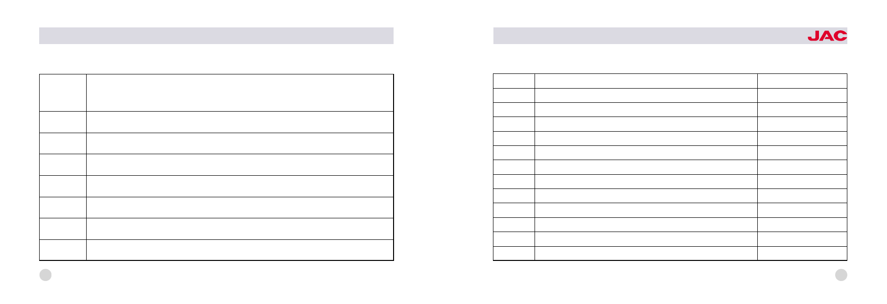
Table two: Description of the oil in lubricating table (for reference)

Symbol

in the table

J

H

Lubricant

L-ECC grade GB11122-89

industrial vaseline

G

GB491-87 2# lime base grease

ZL

GB5671-85 universal lithium base grease

B

half HV-20 gasoline engine oil 渊GB2537冤 and half 45# transformer oil 渊GB2536冤

Y

brake fluid JG3渊GB10830冤

Z

medium-load vehicle gear oil渊GL-4冤 85W/90

80

HFC1020

series trucks

Number

1

12

Name

Nuts connected the transmission and the clutch housing

Fixing nuts of steering wheel

Tightening torque渊N窑m冤

80-110

54-68.6

2

Intermediate driveshaft flange nuts

46-62

3

Nuts of steering tie rod ball pin

98-127

4

Nuts of steering drop arm

196-250

5

Transmission flange nuts

180-220

6

Diving gear flange nuts

245-274.4

7

Nuts on the tyre

287-346

8

U-bolt of the front leaf spring

157-216

9

U-bolt of the rear leaf spring

157-216

10

Fixing nuts of the steering straight arm

316依35

11

Fixing nuts of steering flexural arm

316依35

Table three: Tightening torque of main fastening pieces (for reference)

81

82

HFC1020

series trucks

JAC INTERNATIONAL
Add: NO. 18. Hepai Road, Hefei, China

Post Code: 230601

Tel:渊86 551冤2296360

Fax: 渊86 551冤2296454

http://www.jac.com.cn

( 玉 ). Use of instruments
and apparatuses in the cab

1. Integrated switch and instru鄄
ment cluster

Integrated switch

(figure below)

which is composed of steering shaft
lock seat尧ignition start lock and
combination switch lies underneath
the steering wheel.

1) Ignition switch
Ignition switch is on the right side of
integrated switch. It has four func鄄
tions: LOCK尧ACC尧ON尧START. When
the key is on the 'LOCK' position,
the ignition switch has been connect鄄
ed to the power source and the
lockup of steering gear has been
disengaged. Turn the key to 'ACC'
position clockwise, the circuit of ac鄄
cessories like radio and tape player
can be connected. Turn to the 'ON'
position, and the instrument circuit is
connected. If keep on turning until to
the 'START' position, the engine can
be started. You should unlash the
handle of the key immediately after
the engine started. And the key can
return to the 'ON' position by the ac鄄

tion of spring. The schematic dia鄄
gram of ignition switch is as follows.

2) Combination switch ( left control
handle)

left control handle

schematic diagram of ignition switch

combination
switch

ignition switch

schematic diagram of integrated switch

2

HFC1048

series trucks

Combination switch is under the
control of the multifunction handle,
which lies in the lower left and inferi鄄
or place of the steering wheel. It can
control small light尧headlight尧head鄄
light dimmer and turning to the left or
the right by two different movement
modes. The symbol and function of
the combination switch is as follows:
淤 The OFF symbol indicates that
small light and headlight do not light.
(But at this time the high beam can
light if you put up the handle.)
于 The

symbol is the indica鄄

tion of small light. Turn the control
handle clockwise by 30毅 ,and the
front尧rear small lights and the instru鄄
ment light can light.
盂 The

symbol is the indica鄄

tion of headlight. Keep on the turning
of the left control handle clockwise
by 30毅 , the front headlight尧the rear
small light and the instrument light
can light.
榆 The

symbol is the indica鄄

tion of steering. Forward and back鄄
ward motion of the control handle
can operate the left and right turning
lamp and the turn light indicator in
the instrument panel. Push the con鄄
trol handle forward in the horizontal
direction, the right turning lamp lights
and there has the indication of turn鄄
ing right in the instrument panel. On
the other hand, pull the control han鄄
dle backward, the left turning lamp
lights and there has the indication of
turning left in the instrument panel. If

the control handle is in the middle
position, then there has no indication
of turning.
虞 Dimmer of headlight: Lift the left
control handle upwards gently and
do the 'uplift -looseness' motion, it
can control the dimmer function of
the headlight. Uplift the handle once,
high beam headlamp lights; loose
the handle, it goes out. Repeating
the above action can control the
work status of the high beam head鄄
lamp to obtain the purpose of dim鄄
mer function when overtaking or
passing in night.

3

4

3)Combination switch (right control
handle)

淤 The

symbol is indication of

the scrubber. When the washer con鄄
trol button on the top of the control
handle pressed, the cleaning mixture
(using antifreeze fluid in winter) in the
window washer which lies in the right
doorframe and underneath instru鄄
ment panel can be spouted to the
windshield glass through the spout
under the window.
于 The

symbol is indication of

the wiper. Turning the control handle
clockwise in the horizontal direction
can control the wiper. Turn the con鄄
trol handle clockwise by 12毅 to the
'LO' position, then the wiper works
with low speed. Keep the turning
clockwise for another 12毅, the wiper
can work with high speed. When the
control handle is on the original posi鄄
tion, it can be disconnected or re鄄
turned automatically.
盂 The

symbol is indication of

exhaust throttle assistant braking. Lift
the right control handle upwards and
do the 'uplift-looseness' motion. Up鄄
lift the handle, then the switch can be
connected and the indicator lamp in
the instrument panel lights. This
shows that exhaust throttle assistant

braking works. If the accelerator
pedal or the clutch pedal was
stepped, the exhaust assistant brak鄄
ing should cancelled automatically
and the indicator lamp in the instru鄄
ment panel went out.
4) Other electric appliance switch (
seen in the left and below figure)
Other electric appliance switches
mainly include horn button, danger
warning switch, fog lamp switch,
courtesy lamp switch and ceiling
light switch.
淤 The horn button is in the center of
steering wheel, when the button is
depressed it can hoot.
于 The

symbol ( the right and

below figure) is indication of danger
warning switch. If the button is de鄄

right control handle

HFC1048

series trucks

5

pressed, the front尧 rear尧 left尧 right
turning lamp flash at the same time
and send out emergency signal for
alarm indication. Press the button a鄄
gain, reset signal of the switch dis鄄
connected.
盂 The

symbol ( the right and

below figure) is indication of the fog
lamp. If pressed, the fog lamp lights.
Press again, the switch resets.
榆 Ceiling light signal indicates that
the door of the vehicle is shut closely
or not. When there have one door
opened or did not shut closely, the
ceiling lamp lights to remind driver.

5) instrument cluster

danger alarm and fog lamp switch

other electric appliance switch

instrument cluster(air brake)

instrument cluster(hydraulic brake)


Content   ..  1300  1301  1302  1303   ..