Isuzu N-Series. Manual - part 128


  Index      Isuzu     Isuzu N-Series - service repair manual


Search            


Content   ..  126  127  128  129   ..


Isuzu N-Series. Manual - part 128


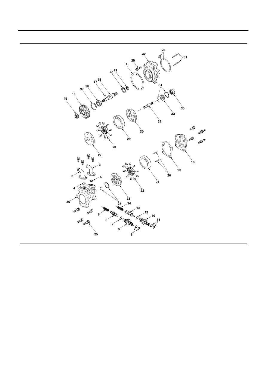
POWER STEERING 3B1-31

Tandem Hydraulic Pump

N3A0242E

3B1-32 POWER STEERING

Disassembly

1. O-ring
2. Hose Connector: HBB
3. Hose Connector: P/S
4. O-ring
5. Connector: HBB
6. O-ring
7. O-ring
8. Valve
9. Spring

10. Connector: P/S
11. O-ring
12. O-ring
13. Valve
14. Spring
15. Nut
16. Gear
17. Key
18. Rear Body
19. Gasket
20. Pin
21. Cam
22. Rotor and Vane: P/S
23. Pressure Plate
24. O-ring
25. Bolt
26. O-ring
27. Side Plate

28. Rotor and Vane: HBB
29. Cam
30. Pressure Plate
31. Pin
32. Shaft
33. Retainer
34. O-ring
35. Oil Seal
36. Pump Housing

• Use a brass drift to remove the oil seal from the

pump housing.

37. Snap Ring

• Use a mallet to remove the shaft assembly from

the front body.

38. Ball Bearing
39. Shaft

• A press and rod will be necessary to remove the

ball bearing from the shaft.

40. Retainer Ring
41. Oil Seal
42. Front Body

• Use a brass drift to remove the oil seal from the

front body.

Clean

• All parts in a suitable solvent and blow dry with

compressed air. Be sure to use clean solvent to
clean internal parts.

Inspection

• Cartridge assembly

Legend

1. O-ring

23. Pressure plate

2. Hose connector: HBB

24. O-ring

3. Hose connector: P/S

25. Bolt

4. O-ring

26. O-ring

5. Connector: HBB

27. Side Plate

6. O-ring

28. Rotor and vane: HBB

7. O-ring

29. Cam

8. Valve

30. Pressure plate

9. Spring

31. Pin

10. Connector: P/S

32. Shaft

11. O-ring

33. Retainer

12. O-ring

34. O-ring

13. Valve

35. Oil seal

14. Spring

36. Pump housing

15. Nut

37. Snap ring

16. Gear

38. Ball bearing

17. Key

39. Shaft

18. Rear body

40. Retainer ring

19. Gasket

41. Oil seal

20. Pin

42. Front body

21. Cam

P/S: Power steering

22. Rotor and vane: P/S

HBB: Hydraulic booster brake

POWER STEERING 3B1-33

– Vane tips of cartridge assembly for wear.
– Vanes for scoring or wear.
– Inner surface of the ring for scoring, wear, dam-

age, etc.

– Fit of the vanes in the rotor. The vanes must fit

property in the rotor slots, without sticking or
excessive play. Also check for burrs in the rotor
slots, and excessive wear at the thrust faces.

– If heavy wear is present, or if parts are dam-

aged, replace the entire cartridge assembly.

• Side place for wear at the thrust faces.

Replace if excessive wear is evident.

• Ball bearing. If the bearing is rough or loose, re-

place it.

• Seal contact area of the shaft. If fretting or rough-

ness is present, replace the shaft.

• Gear for rough or chipped teeth.
• Flow control valve assembly for scoring or burrs.

Also, inspect the flow control valve bore in the
pump housing for burrs.

If heavy damage is present, replace pump housing as-
sembly together with valves.

Reassembly

1. Oil Seal
2. Front Body

• Oil seal into the front body using a proper size rod

and press or hammer.

3. Shaft
4. Ball Bearing

• Press the shaft, into the ball bearing as illustration.

5. Retaining Ring

• Place the retaining ring in the front body and install

the shaft assembly into the front body using a
press or hammer.

6. Snap Ring

• Snap ring into front body.

7. Oil Seal
8. Pump Housing

• Oil seal into pump housing using a proper size rod

and press or hammer.

9. O-ring

10. Retainer
11. Shaft
12. Pressure Plate
13. Cam
14. Rotor and Vane: HBB
15. Side Plate
16. Pin

• Set pressure plate, cam, rotor and vane, side plate,

and pins into pump housing as illustration.

Legend

1. Shield plate
2. Stamping

N3A0244E

N3A0245E

N3A0246E

3B1-34 POWER STEERING

17. O-ring
18. Bolt

• Attach O-rings into front body grooves and assem-

ble front body and pump housing by tightening
bolts.

Tighten:

• Bolt and nut to

4 (four) bolts: 54 N

⋅m (5.5 kg⋅m / 40 lb⋅ft)

1 (one) bolt: 25 N

⋅m (2.5 kg⋅m / 18 lb⋅ft)

19. O-ring
20. Pressure Plate
21. Rotor and Vane: P/S
22. Cam
23. Pin

• Set pressure plate, rotor and vane, cam and pins

into pump housing as illustration.

24. Gasket
25. Rear Body

Tighten:

• Bolt and nut to 34 N

⋅m (3.5 kg⋅m / 25 lb⋅ft)

26. Key
27. Gear
28. Nut

• Key, gear and nut onto shaft.
• The long hub of the gear faces front body.

Tighten:

• Bolt and nut to 103 N

⋅m (10.5 kg⋅m / 76 lb⋅ft)

29. Spring
30. Valve
31. O-ring
32. O-ring
33. Connector: P/S

• Spring, valve, O-ring, O-rings and connector into

pump housing.

Tighten:

• Bolt and nut to 54 N

⋅m (5.5 kg⋅m / 40 lb⋅ft)

34. Spring
35. Valve
36. O-ring
37. O-ring
38. Connector: HBB

• Spring, valve, O-ring, O-rings and connectors into

pump housing.

Tighten:

• Bolt and nut to 54 N

⋅m (5.5 kg⋅m / 40 lb⋅ft)

39. O-ring
40. Hose Connector: P/S
41. Hose Connector: HBB

Tighten:

• Bolt and nut to 21 N

⋅m (2.1 kg⋅m / 15 lb⋅ft)

42. O-ring

Legend

A. Front view
B. Rear view

1. Pressure plate
2. Cam, Rotor and vane
3. Side plate
4. Oblong hole
5. Stamping

Legend

A. Front view

1. Pressure plate
2. Rotor and vane, Cam
3. Oblong hole
4. Stamping

N3A0247E


Content   ..  126  127  128  129   ..