Isuzu N-Series. Manual - part 122


  Index      Isuzu     Isuzu N-Series - service repair manual


Search            


Content   ..  120  121  122  123   ..


Isuzu N-Series. Manual - part 122


POWER STEERING 3B1-7

Power Steering Unit

Removal

1. Remove the head light assembly. (for Non-Tilt Cab

Model, driver side only) Refer to “Headlight Re-
placement”.

2. Remove the under panel. (for Non-Tilt Cab Model)
3. Remove the front bumper assembly. (for Non-Tilt

Cab Model)

4. Remove the oil pipe.

Before disconnecting the oil pipe, clean the steer-
ing unit paying particular attention to the area
around the joint and plug or tape the oil port after
disconnecting the pipe to prevent entry of dust or
other foreign matter.
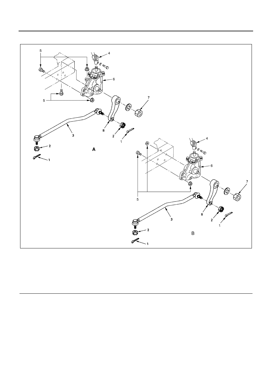
Legend

A. NHR, NKR

4. Universal joint

B. NPR, NQR, NPS

5. Unit fixing nut and bolt

1. Cotter pin

6. Power steering unit

2. Nut

7. Nut

3. Drag link

8. Pitman arm

N3A0447E

3B1-8 POWER STEERING

5. Cotter Pin
6. Nut
7. Drag Link

Disconnect the drag link at the knuckle arm and the
pitman arm.
Remover: 5-8840-2017-0

8. Universal Joint

Apply a setting mark (1) across the yoke and worm
shaft in unit to ensure reassembly of the parts in
the original position.

9. Unit Fixing Bolt and Nut

10. Power Steering Unit
11. Nut
12. Pitman Arm

Apply a setting mark (1) across the pitman arm and
worm shaft.

Puller: 5-8840-2051-1

N3A0122E

N3A0123E

N3A0124E

N3A0125E

POWER STEERING 3B1-9

Installation

1. Pitman Arm

Align the setting mark (1) applied at removal.

2. Nut

Tighten:

• Pitman arm nut to

NHR, NKR Rigid suspension: 216 N

⋅m (22 kg⋅m / 159

lb

⋅ft)

NPR, Wishbone suspension: 294 N

⋅m (30 kg⋅m / 217

lb

⋅ft)

3. Power Steering Unit
4. Unit Fixing Nut and Bolt

Tighten:

• Nut and bolt to 103 N

⋅m (10.5 kg⋅m / 76 lb⋅ft)

5. Universal Joint

Install the parts by aligning setting marks (1) ap-
plied at removal.

Tighten:

• Universal joint bolt to

M8 bolt: 25 N

⋅m (2.5 kg⋅m / 18 lb⋅ft)

6. Drag Link
7. Nut
8. Cotter Pin

1) Install the drag link to the pitman arm and the

knuckle arm.

2) Tighten nuts to specified torque, with just

enough additional torque to align cotter pin
holes. Install new cotter pin.

N3A0126E

N3A0125E

N3A0128E

N3A0124E

3B1-10 POWER STEERING

Tighten:

• Nut to 167 N

⋅m (17 kg⋅m / 123 lb⋅ft)

• Connect the oil pipe. Tighten flare nuts to specified

torque.

Tighten:

• Flare nut to 44 N

⋅m (4.5 kg⋅m / 33 lb⋅ft)

9. Install the bumper assembly. (for Non-Tilt Cab

Model)

Tighten:

• Bumper bolt to 40 N

⋅m (4.1 kg⋅m / 30 lb⋅ft)

10. Install the under panel. (for Non-Tilt Cab Model)
11. Install the head light assembly, front grille and front

combination light assembly. (for Non-Tilt Cab Mod-
el) Refer to “Headlight Replacement”.

Notice:
After installation, adjust head light aiming. Refer to “Cab
and Chassis Electrical”. (Non-Tilt Cab Model)

Power Steering Pump

Preparation

• Drain the fluid through the pipe which is connected

to the return board for the power steering pump.

• Disconnect the fluid piping.

Removal

4J Series Engine

• Loosen the idler pulley locking nuts (1) for the pow-

er steering pump.

• Loosen the adjusting bolts for the drive belt and re-

move the drive belt.

• Remove the pipe brackets (2) and clips (3) on the

alternator side.

• Remove the pump mounting brackets.

4HE1 Engine

• Block the vehicle wheels and apply the parking

brake.

• Disconnect the battery ground cable.

1. Disconnect air intake hose at turbocharger side.
2. Raise the vehicle and remove front exhaust pipe

with exhaust brake.

• Remove bolts at manifold, silencer and support

bracket.

3. Place a container under the hydraulic pump as-

sembly to catch fluid when disconnecting hoses.
Clean the surfaces around fittings before removing
them. 

4. Remove power steering outlet flexible hose (1) and

nut.

5. Remove hydraulic booster outlet pipe (2) nut.
6. Remove two clips for hydraulic booster lines on the

flywheel housing.

7. Remove clip for hydraulic booster lines on the left

side member.

8. Hydraulic booster inlet hose (3).
9. Power steering inlet hose (4).

10. Remove hydraulic booster pipe from the pump.
11. Remove hydraulic pump assembly with bracket

and O-ring.

N3A0132E

N3A0135E


Content   ..  120  121  122  123   ..