Isuzu N-Series. Manual - part 1198


  Index      Isuzu     Isuzu N-Series - service repair manual


Search            


Content   ..  1196  1197  1198  1199   ..


Isuzu N-Series. Manual - part 1198


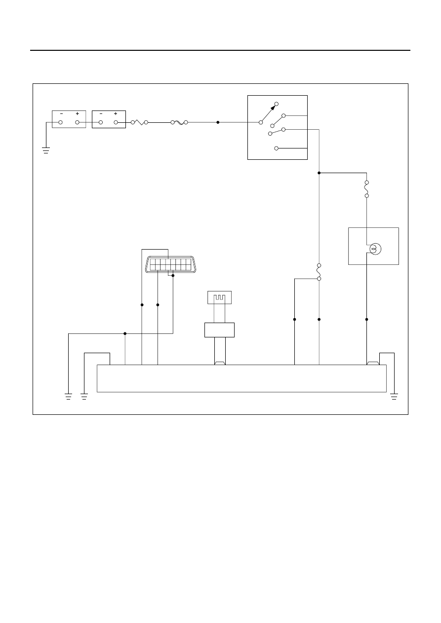
SRS CONTROL SYSTEM 9C-39

DTC: 25  SRS Airbag Deployment Circuit is Shorted to Ignition Voltage

Outline

Description of Circuit
Turn the starter switch to “ON”. SRS control unit per-
forms the tests to diagnose critical function fault in the
SRS control unit. Upon completion of the tests, when the
results are pass, “Ignition” voltage and deployment cir-
cuit voltage will be measured to check they are within
the normal range. SRS control unit detects battery volt-
age short circuit in the SRS airbag circuit by monitoring
the voltage of “Airbag low” terminal “8”.

Condition when DTC is Set
When “Ignition” is within the normal operational voltage
but the voltage of “Airbag low” exceeds the specified val-
ue, the DTC 25 is set.

Action to be Taken
SRS control unit turns the “SRS” warning lamp ON and
set the DTC 25.

Condition when DTC is Cleared
When this function fault disappears after SRS control
unit replacement.

B

ACC

ON

ST

STARTER SWITCH

METER

AIRBAG

SRS CONTROL UNIT

DATA LINK CONNECTOR

16 15 14 13 12 11 10 9

8 7 6 5 4 3 2 1

0.5

B

0.5

GY

0.5

SB

0.5

GY

0.5

SB

16

4

19

15

18

7

8

20

6

5

0.85B

0.85B

0.5

B/R

0.5

B/R

0.5

W/R

0.5

B/R

0.5

B/R

0.5

W/R

0.5

B

1.25

B

2L

3
B/Y

2

14

3W/L

8B

3W/L

40A
KEY SW

10A
SRS

AIRBAG

SRS COIL

ASSEMBLY

1

2

2

1

0.5

Y

0.5

Y/B

3

10A
METER

0.5
B/Y

18

OFF

N9A0086E

9C-40 SRS CONTROL SYSTEM

Description of DTC Chart Test
Numbers below indicate step numbers in the diagnostic
chart.
2. This test is to check if the location of function fault is
in the SRS airbag deployment circuit.
3. This test is to check if the location of function fault is
in the SRS airbag deployment circuit.
4. This test is to check if the location of function fault is
in the SRS coil.
5. This test is to check if the location of function fault is
in the SRS coil assembly or SRS airbag.

Point of Diagnosis
In the situations that the trouble appears intermittently, it
may be caused by battery voltage short circuit in the
SRS airbag circuit.
Carefully check the SRS airbag deployment circuit for
wire breakage or exposed wire. If the lead wire and SRS
coil assembly of SRS airbag are damaged, the part must
be replaced. To prevent the replaced SRS control unit
from damage, carefully check the SRS airbag deploy-
ment circuit including SRS coil assembly and SRS
airbag.

Caution:

When this DTC is set, all the SRS system parts (SRS
control unit, airbag, etc.) must be replaced. In addition,
This DTC cannot be cleared. Be sure to disconnect the
battery cable before replacement, otherwise it will result
malfunction of replaced SRS system parts or cause bat-
tery short circuit.

Step

Action

Value

YES

NO

1

Has the “SRS system check” been per-
formed? 

Go to Step2

Go to “SRS sys-

tem check”.

2

1. When measurement is required in this

chart, use 5-8840-0366-0 DMM.

2. Turn the starter switch to OFF.
3. Remove the 2-pole connector (yellow) of

SRS coil assembly located in the lower
portion of steering column.

4. Remove the SRS control unit.
5. Measure the resistance between the

SRS control unit harness connector ter-
minals “8” and “20” (ignition).

Does the 5-8840-0366-0 DMM indicate “OL”
(infinity)?

Go to Step3

Replace the SRS 

harness. Go to 

Step6

3

Measure the resistance between the SRS
control unit harness connector terminals “7”
and “20” (ignition).

Does the 5-8840-0366-0 DMM indicate “OL”
(infinity)?

Go to Step4

Replace the SRS 

harness. Go to 

Step6

4

1. Turn the starter switch to OFF.
2. Remove the 2-pole connector (yellow) of

SRS airbag harness located in the upper
portion of steering column.

3. Reconnect the SRS coil assembly har-

ness connector to the lower portion of
steering column.

4. Measure the resistance between the

SRS control unit harness connector ter-
minals “8” and “20” (ignition).

Does the 5-8840-0366-0 DMM indicate “OL”
(infinity)?

Go to Step5

Replace the coil 

assembly.Go to 

Step7

SRS CONTROL SYSTEM 9C-41

5

Measure the resistance between the SRS
control unit harness connector terminals “7”
and “20” (ignition).

Does the 5-8840-0366-0 DMM indicate “OL”
(infinity)?

Replace the 

driver’s airbag 

assembly. Go to 

Step6

Replace the coil 

assembly.Go to 

Step6

6

Reconnect all the parts, and check that those
are installed properly.

Are all the parts installed properly?

Turn the starter 

switch to OFF. 

Replace the SRS 

control unit. Go to 

Step7

Go to Step6

7

1. Reconnect all the parts, and check that

those are installed properly.

2. Clear the DTC.

Is this step completed?

Check the repair.

Go to Step7

Step

Action

Value

YES

NO

9C-42 SRS CONTROL SYSTEM

DTC: 26  SRS Airbag Deployment Circuit is Open

Outline

Description of Circuit
Turn the starter switch to “ON”. SRS control unit per-
forms the tests to diagnose critical function fault in the
SRS control unit. Upon completion of the tests, when the
results are pass, “Ignition” voltage and deployment cir-
cuit voltage will be measured to check they are within
the normal range. SRS control unit detects open circuit
in the SRS airbag circuit by monitoring the voltage of
“Airbag low” terminal.

Condition when DTC is Set
When the voltage of “Airbag low” terminal is within a cer-
tain range.

Action to be Taken
SRS control unit turns the “SRS” warning lamp ON and
set the DTC 26.

Condition when DTC is Cleared
When the voltage of “Airbag low” terminal is out of a cer-
tain range.

Description of DTC Chart Test
Numbers below indicate step numbers in the diagnostic
chart.
2. This test is to check if the 2-pole connector (yellow)
located in the lower portion of steering column is proper-
ly connected.
3. This test is to check the 2-pole connector (yellow) lo-
cated in the lower portion of steering column for secure
contact and/or corrosion.
4. This test is to check if the location of function fault is
up to the 2-pole connector (yellow) located in the lower
portion of steering column.
5. This test is to check if the wire is open.
6. This test is to check if the location of function fault is
in the SRS coil assembly or SRS airbag.

Point of Diagnosis
In the situations that the trouble display appears inter-
mittently, it may be caused by improper connection be-
tween 2-pole connector terminals “1” and “2” of SRS
airbag harness located in the upper portion of steering
column, between 2-pole connector terminals “1” and “2”
of SRS coil assembly harness, between SRS control
unit terminals “7” and “8”, or open circuit in the SRS
airbag deployment circuit.

SRS CONTROL UNIT

AIRBAG

SRS COIL

ASSEMBLY

1

2

2

1

0.5

Y

0.5

Y/B

8

7

N9A0076E


Content   ..  1196  1197  1198  1199   ..