Content .. 1194 1195 1196 1197 ..
Isuzu N-Series. Manual - part 1196
SRS CONTROL SYSTEM 9C-31
Point of Diagnosis
In the situations that the trouble display appears inter-
mittently, it may be caused by improper connection be-
tween 2-pole connector terminals “1” and “2” of SRS coil
located in the lower portion of steering column, between
2-pole connector terminals “1” and “2” of SRS airbag lo-
cated in the upper portion of steering column, between
SRS control unit terminals “7” and “8”, or between the
wire and terminal in SRS airbag deployment circuit.
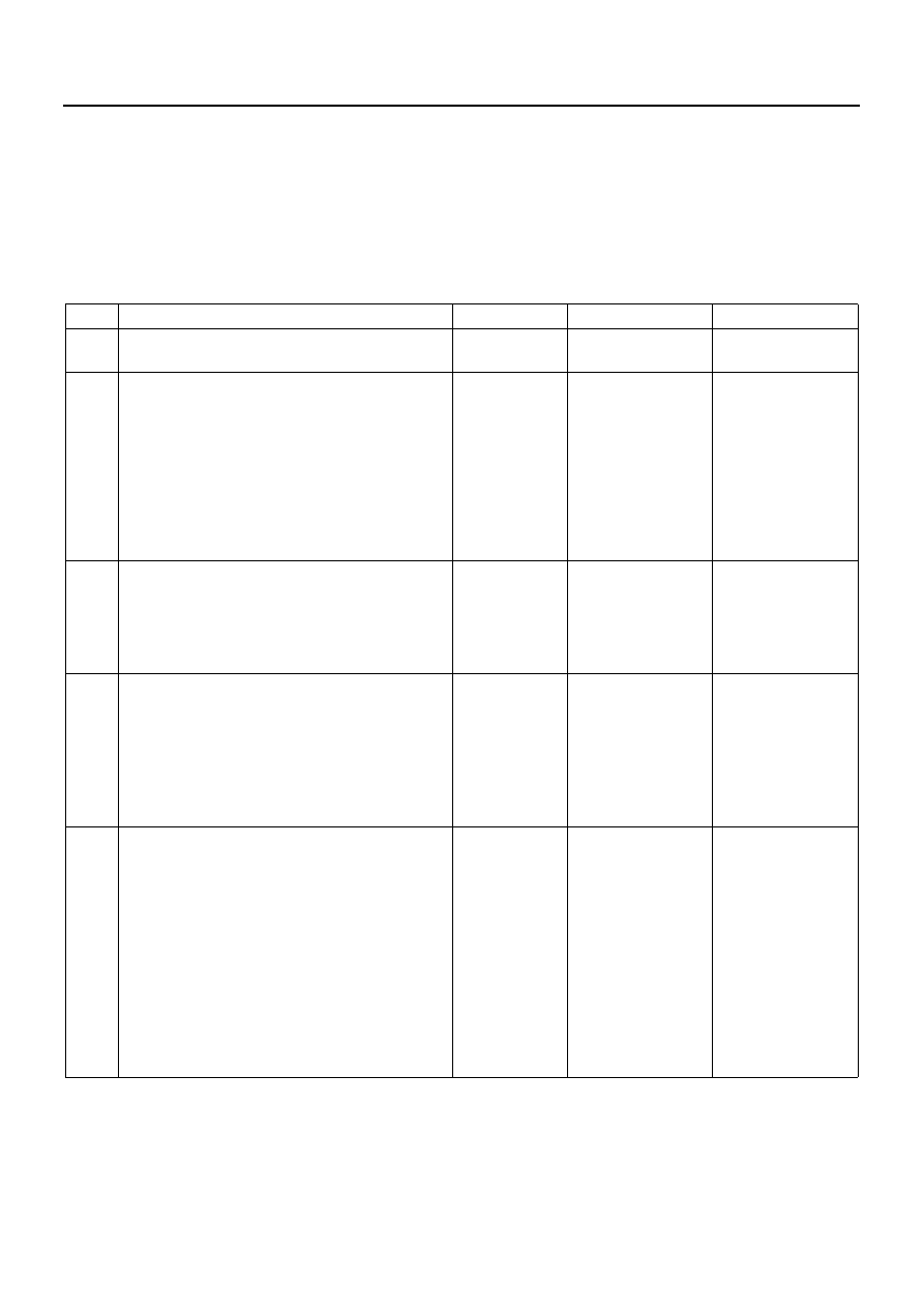
Step
Action
Value
YES
NO
1
Has the “SRS system check” been per-
formed?
—
Go to “SRS sys-
tem check”.
2
1. When measurement is required in this
chart, use 5-8840-0366-0 DMM and ap-
propriate terminal adapter in 5-8840-
0385-0 Connector test adapter kit.
2. Using the data list function of Tech 2,
read the resistance in airbag deployment
circuit and record it.
Does the resistance in airbag deployment cir-
cuit exceed specified value?
7.2
Ω
Go to Chart A
SRS control unit
function check.
3
1. Turn the starter switch to OFF.
2. Check the 2-pole connector (yellow) of
SRS coil located in the lower portion of
steering column for proper connection.
Is the 2-pole connector connected properly?
—
Connect the 2-
pole connector of
SRS coil assem-
bly properly.Go to
4
1. Remove the 2-pole connector (yellow) of
SRS coil located in the lower portion of
steering column for inspection.
2. If it is normal, reconnect the 2-pole con-
nector of SRS coil assembly properly.
3. Turn the starter switch to ON.
Is DTC 21 detected as current trouble?
—
5
1. Turn the starter switch to OFF.
2. Remove the 2-pole connector (yellow) of
SRS coil assembly located in the lower
portion of steering column.
3. Connect the 5-8840-2421-0 SRS substi-
tute load and an appropriate terminal
adapter in the 5-8840-0385-0 Connector
test adapter kit to the SRS harness side
connector which connects to SRS coil as-
sembly.
4. Turn the starter switch to ON.
Is DTC 21 detected as current trouble?
—