Content .. 1155 1156 1157 1158 ..
Isuzu N-Series. Manual - part 1157
8-340 CAB AND CHASSIS ELECTRICAL
Installation
To install, follow the removal steps in the reverse order.
SRS Control System
General Description
SRS airbag supplements the driver’s seat belt protec-
tion by deploying airbag at the top center of the steering
column.
SRS airbag deploys in case of front collision over certain
degree of impact.
This system consists of SRS control unit, driver’s SRS
airbag, SRS coil assembly, exclusive wire harness, and
“SRS” warning lamp in the meter and forms a deploy-
ment circuit.
A sensor is equipped to this circuit to convert the impact
into an electrical signal in case of front collision over cer-
tain degree of impact. The electrical signal generated at
this time will be processed in the SRS control unit to
compare with the value stored in the memory.
When the generated signal exceeds the setting value,
SRS control unit sends sufficient current to SRS airbag
for deployment.
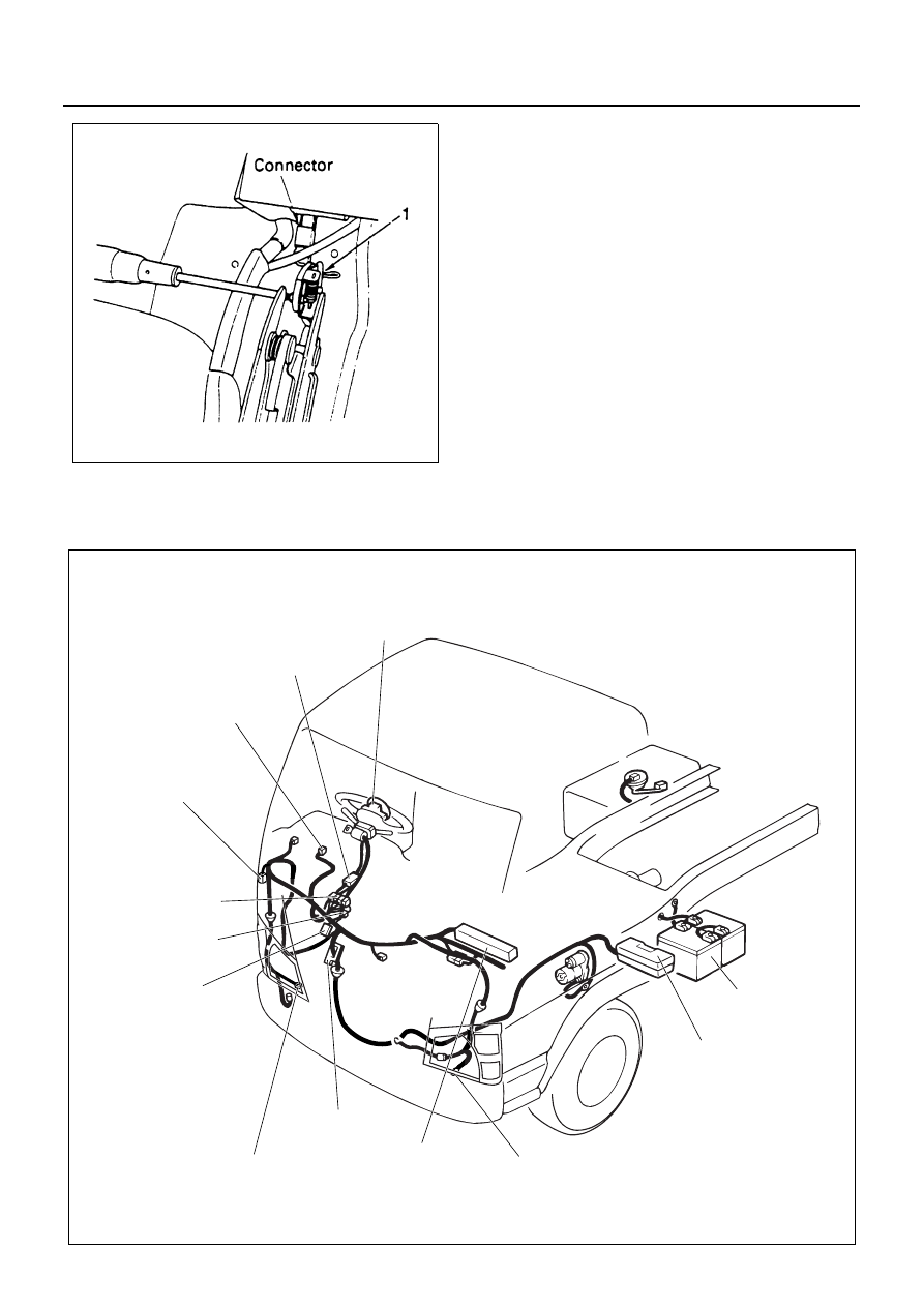
Parts Location
N8A0364E
A-1 AIR BAG
BATTERY
FL-2 FUSIBLE LINK
B-1 EARTH; FRAME LH (FRONT)
FUSE BOX ASM
F-16, F-18
B-79 DATA LINK CONNECTOR
B-51 SRS WARNING LIGHT
(METER)
B-244 SRS COIL
B-67
B-276 SRS COUPLING
CONNECTOR
B-243 SRS CONTROL UNIT
H-7
B-275 EARTH; FRAME RH (FRONT)
N9A0066E