Isuzu N-Series. Manual - part 1156


  Index      Isuzu     Isuzu N-Series - service repair manual


Search            


Content   ..  1154  1155  1156  1157   ..


Isuzu N-Series. Manual - part 1156


8-336 CAB AND CHASSIS ELECTRICAL

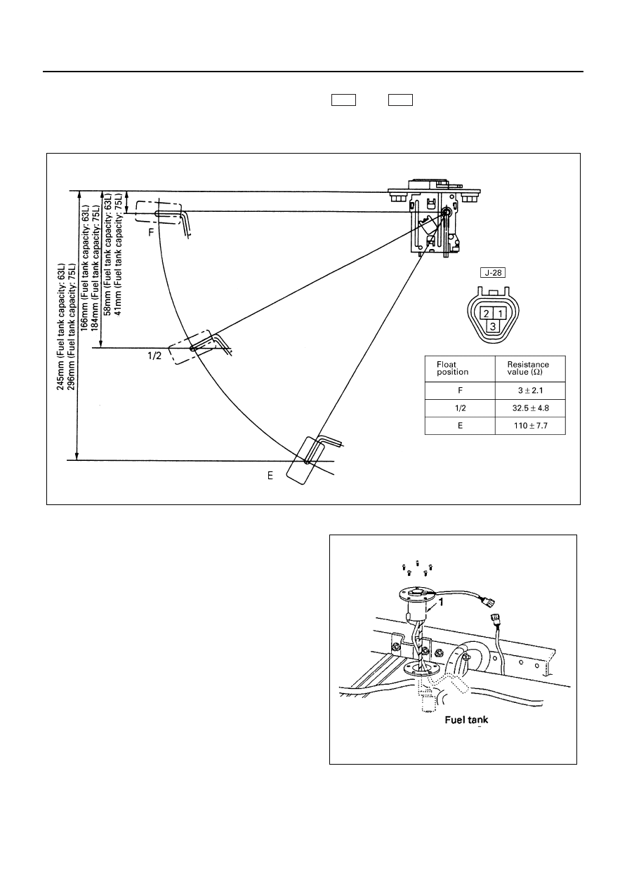
(Float type of warn low fuel level)

1. Check the resistance between the connector terminals 1 

 and 3 

 while shifting the float from “E” to “F”

point.

2. Check if the low fuel warning light turns on when the float is at “E” position. If found defective replace the fuel

tank unit.

Removal
Preparation:
Disconnect the battery ground cable.

1. Fuel Tank Unit

1) Disconnect the connector.
2) Remove five screws.

Installation
To install, follow the removal steps in the reverse order.

J-28

J-28

N8A5414E

N8A5415E

CAB AND CHASSIS ELECTRICAL 8-337

Engine Speed Sensor

Inspection
Measure the resistance value between the engine
speed sensor connector terminals.
Replace the engine speed sensor when the result of
inspection is found abnormal.
4J Series engine = 1.36 — 1.86 K

4H Series engine = 0.57 — 0.86 K

Removal
Preparation:
Disconnect the battery ground cable.

1. Engine Speed Sensor

1) Disconnect the connector.
2) Remove the engine speed sensor.

Installation
To install, follow the removal steps in the reverse order.

Vacuum Switch

Inspection
When the pressure value is below 250

±30 mm Hg

(33.3

±4.0 kPa), check to see if there is continuity be-

tween the terminal and the ground. If no continuity, re-
place the switch with a normal one.

Removal
Preparation:
Disconnect the battery ground cable.

1. Vacuum Switch

1) Disconnect the connector.
2) Remove the vacuum switch.

Installation
Apply liquid gasket to the screw portion of the switch to
prevent vacuum leak.

N8A0355E

N8A5417E

N8A0357E

N8A5419E

8-338 CAB AND CHASSIS ELECTRICAL

Vacuum Warning Buzzer

Inspection
Apply battery voltage to the buzzer connector terminals
to check the buzzer sound.
Replace the buzzer when the result of inspection is
found abnormal.
Removal
Preparation:
Disconnect the battery ground cable.

1. Meter Assembly

Refer to “METER ASSEMBLY” in this section.

2. Vacuum Warning Buzzer

1) Disconnect the connector.
2) Remove the buzzer fixing screw.

Installation
To install, follow the removal steps in the reverse order.

Water Sedimenter Switch

Inspection

1. When the float in the water sedimenter is above the

drain warning level, confirm if there is continuity be-
tween the switch connector terminals.

2. Turn the starter switch on, disconnect the water

sedimenter connector and connect the harness
side connector terminals. Then confirm that the
sedimenter warning light turns on.
If found defective, replace the switch or repair a
poor connection or an open circuit between the
connector terminals.

Brake Fluid Switch

Inspection

1. Confirm there is continuity between the switch con-

nector terminals when the brake fluid in the tank is
between 60 — 75 cc level.

2. Turn the switch on, disconnect the brake fluid

switch connector and connect the harness side
connector terminals. Then confirm that brake
warning light turns on.
If found defective, replace the tank, or repair a poor
connection or an open circuit between the connec-
tor terminals.

Removal
Preparation:
Disconnect the battery ground cable.

1. Instrument Panel Assembly

Refer to “INSTRUMENT PANEL” of section 2.

2. Brake Fluid Tank (Brake Fluid Switch)

1) Disconnect the switch connector.
2) Remove four fixing nuts.

Legend

1. Meter Assembly
2. Vacuum Warning Buzzer

1

2

N8A0358E

N8A0359E

N8A0360E

CAB AND CHASSIS ELECTRICAL 8-339

3) Drain brake fluid in the tank.
4) Disconnect the tubes.

Caution:
Be very careful not to allow the brake fluid to come in
contact with painted surfaces or resin parts surfaces.

Installation
To install, follow the removal steps in the reverse order,
noting the following points.

1. Bleed the air from brake and clutch fluid pipe line.
2. Check to see if the brake fluid level in the tank with-

in specified level.

3. Check to see if brake warning light comes on when

starter switch is turned on and then warning light
goes off after the engine running.

Parking Brake Indicator Light

The parking brake indicator light is connected in series
with the parking brake switch installed to the parking
brake lever bracket.
The light comes on when the parking brake lever is
pulled, and goes out when the parking brake lever is ful-
ly released.

Notice:
The parking brake indicator light illuminates to warn the
driver that the parking brake is on. This light does not in-
dicate the condition of the operability of the parking
brake.
Circuit Inspection

1. Disconnect the parking brake switch connector.
2. Connect the harness side connector terminal to the

ground.

3. Check to see if the indicator light comes on with the

starter switch “ON”.
Check the bulb or the harness when the result of
inspection is found abnormal.

Parking Brake Switch

Inspection

1. Disconnect the parking brake switch connector.
2. Check to see if there is any continuity between the

switch terminal and the body ground with the circuit
tester connected between them.

Repair the parking brake switch or replace it when the
result of inspection is found abnormal.

Removal
Preparation:
Disconnect the battery ground cable.

1. Parking Brake Switch

1) Disconnect the connector.
2) Remove the fixing screw.

N8A5423E

When parking brake applied

Continuity

When parking brake released

 No continuity

N8A0362E

N8A0363E


Content   ..  1154  1155  1156  1157   ..