Content .. 1091 1092 1093 1094 ..
Isuzu N-Series. Manual - part 1093
8-84 CAB AND CHASSIS ELECTRICAL
H-5
H-6, H-7, H-8
Neutral Switch
Refer to “START AND CHARGING” in this section.
Starter Relay
Refer to “START AND CHARGING” in this section.
Charge Relay
Refer to “START AND CHARGING” in this section.
Starter Switch
Refer to “START AND CHARGING” in this section.
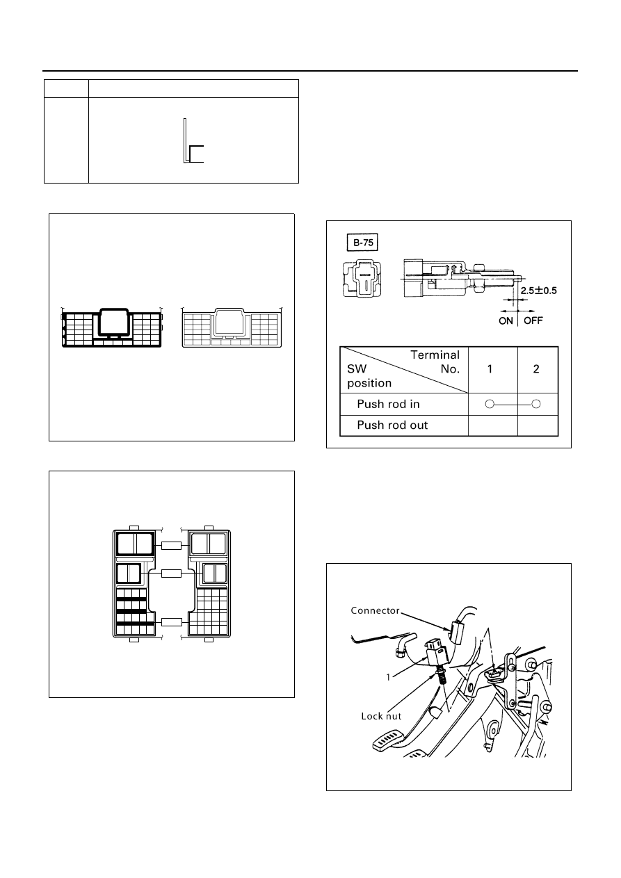
Accel Switch
Inspection
1. Check the continuity between the switch connector
terminals.
2. Check to see if switch push rod operates smoothly.
Repair or replace the accel switch when result of
inspection is found abnormal.
Removal
Preparation:
Disconnect the battery ground cable.
1. Accel Switch
1) Disconnect the connector.
2) Loosen the lock nut of the switch.
3) Remove the switch by turning it.
P-5
(12 V)
No.
Connector Face
000-007
1
2
3
7
8
9
13
14 15
19
20 21
25
26 27
31
32 33
34
35
36
37
4
5
6
10
11 12
16
17 18
22
23 24
28
29 30
38
39 40
6
5
4
12
11 10
18
17 16
24
23 22
30
29 28
40
39 38
3
2
1
9
8
7
15
14 13
21
20 19
27
26 25
33
32 31
34
35
36
37
N8A5488E
1
2
1
2
1 2 3 4
5 6 7 8
9 10 11 12 13
14 15 16 17 18
2
1
2
1
4 3 2 1
8 7 6 5
13 12 11 10 9
18 17 16 15 14
H - 6
H - 7
H - 8
N8A5489E
N8A5091E
N8A0088E