Content .. 1038 1039 1040 1041 ..
Isuzu N-Series. Manual - part 1040
CAB AND CHASSIS ELECTRICAL 8-265
Remove two retaining nuts from right hand side of
pivot.
Installation
To install, follow the removal steps in the reverse order,
noting the following points.
• Temporarily fit the wiper motor by using one of the
four wiper motor fixing screws.
• Put the crank arm ball joint in the wiper link hole
and fix them together while pulling the wiper link.
• Fit the motor with four screws.
• Tighten the pivot nut with the specified torque.
Tighten:
Pivot nut to 8 N
⋅m (80 kg⋅cm/70 lb⋅in)
• Tighten the wiper arm nut with the specified torque.
Tighten:
Wiper arm nut to 17 N
⋅m (170 kg⋅cm/147 lb⋅in)
Wiper Blade Rubber
Removal
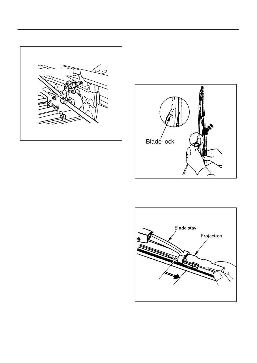
1. Wiper Blade
Push the wiper blade lock while pulling the wiper
blade in the arrow direction.
Notice:
When the wiper blade has been removed, wrap the tip
of the wiper arm with cloth, to avoid damaging the glass.
2. Wiper Blade Rubber
1) Pull the end of rubber and remove the projec-
tion from the click of the blade stay.
2) Pull the rubber out in the same direction.
6
Pivot (Wiper: RH)
N8A0278E
N8A0477E
N8A0280E