Isuzu N-Series. Manual - part 12
POWER TAKE OFF 00-43
Unit Repair
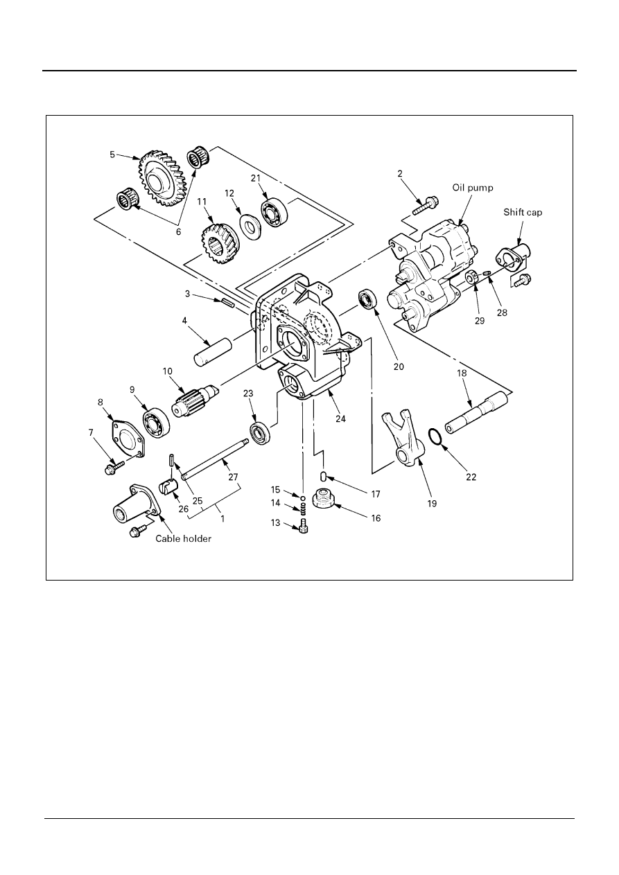
PTO Assembly
Legend
1. Inner rod assembly
16. Interlock plug
2. Bolt
17. Interlock pin
3. Spring pin
18. Shift rod
4. Idle gear shift
19. Shift arm
5. Idle gear
20. Oil seal (output shaft side)
6. Needle bearing
21. Rear ball bearing
7. Bolt
22. O-ring
8. Case cover
23. Oil seal (shift rod side)
9. Front ball bearing
24. Gear case
10. Output shaft
25. Spring pin
11. Output gear
26. Cable connector
12. Thrust collar
27. Inner rod
13. Spring set bolt
28. Spring pin
14. Spring
29. Stopper adapter
15. Ball
NPA0096E