Isuzu Rodeo UE. Manual - part 649
9J1–33
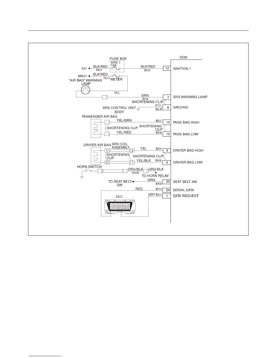
RESTRAINT CONTROL SYSTEM
DTC 25 Driver Deployment Loop Short To Voltage
D09RW002
Circuit Description:
When the ignition switch is turned “ON”, the SDM will
perform tests to diagnose critical malfunctions within
itself. Upon passing these tests, “ignition 1”, and
deployment loop voltages are measured to ensure they
are within their respective normal voltage ranges.
The SDM monitors the voltage at “Driver Bag Low”
terminal “4” and “Passenger Bag Low” terminal “16” to
detect shorts to B+ in the air bag assembly circuits.
DTC Will Set When:
“Ignition 1” is in the normal operating voltage range. This
test is run once each ignition cycle and “Continuous
Monitoring”. Once these conditions are met and the
voltage at “Driver Bag Low” is above a specified value,
DTC 25 will set.
Action Taken:
SDM turns “ON” the “AIR BAG” warning lamp and sets
DTC 25 and also DTC 71
DTC Will Clear When:
The SDM is replaced.
DTC Chart Test Description:
Number(s) below refer to step number(s) on the
diagnostic chart:
2. This test determines whether the SDM is
malfunctioning.
3. This test isolates the malfunction to one side of the
SRS coil assembly yellow 2–pin connector at the
base of steering column.
4. This test determines whether the malfunction is in
CKT IB05–YEL.
5. This test determines whether the malfunction is in
CKT IB06–YEL/BLK.