Isuzu Rodeo UE. Manual - part 647
9J1–25
RESTRAINT CONTROL SYSTEM
DTC 21 Driver Deployment Loop Resistance High
D09RW002
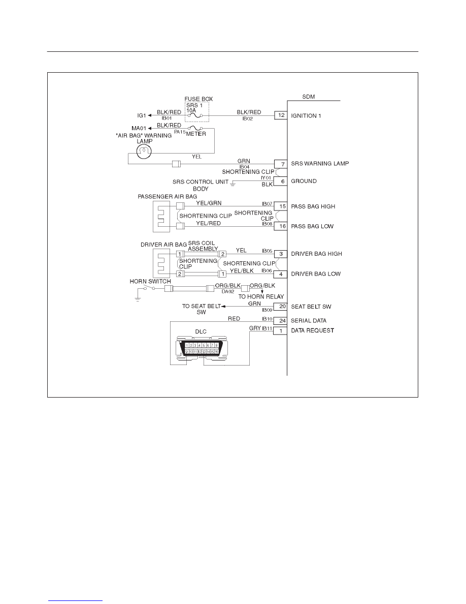
Circuit Description:
When the ignition switch is turned “ON”, the SDM will
perform tests to diagnose critical malfunctions within
itself. Upon passing these tests, “ignition 1”, and
deployment loop voltages are measured to ensure they
are within their respective normal voltage ranges.
The SDM then proceeds with the “Resistance
Measurement Test” “Driver Bag Low” terminal “4” is
grounded through a current sink and the driver current
source connected to “Driver Bag High” terminal “3” allows
a known amount of current to flow. By monitoring the
voltage difference between “Driver Bag High” and “Driver
Bag Low”, the SDM calculates the combined resistance
of the driver air bag assembly, SRS coil assembly,
harness wiring CKTs IB05–YEL and IB06–YEL/BLK, and
connector terminal contact.
DTC Will Set When:
The combined resistance of the driver air bag assembly,
SRS Coil assembly, harness wiring CKTs IB05–YEL and
IB06–YEL/BLK, and connector terminal contact is above
a specified value. This test run once each ignition cycle
during the “Resistance Measurement Test” when:
No “higher priority faults” are detected during
“Turn–ON”
“Ignition 1” voltage is in the specified value.
Action Taken:
SDM turns “ON” the “AIR BAG” warning lamp and sets
DTC 21.
DTC Will Clear When:
The ignition switch is turned “OFF”.