Isuzu Rodeo UE. Manual - part 565
8D–108
WIRING SYSTEM
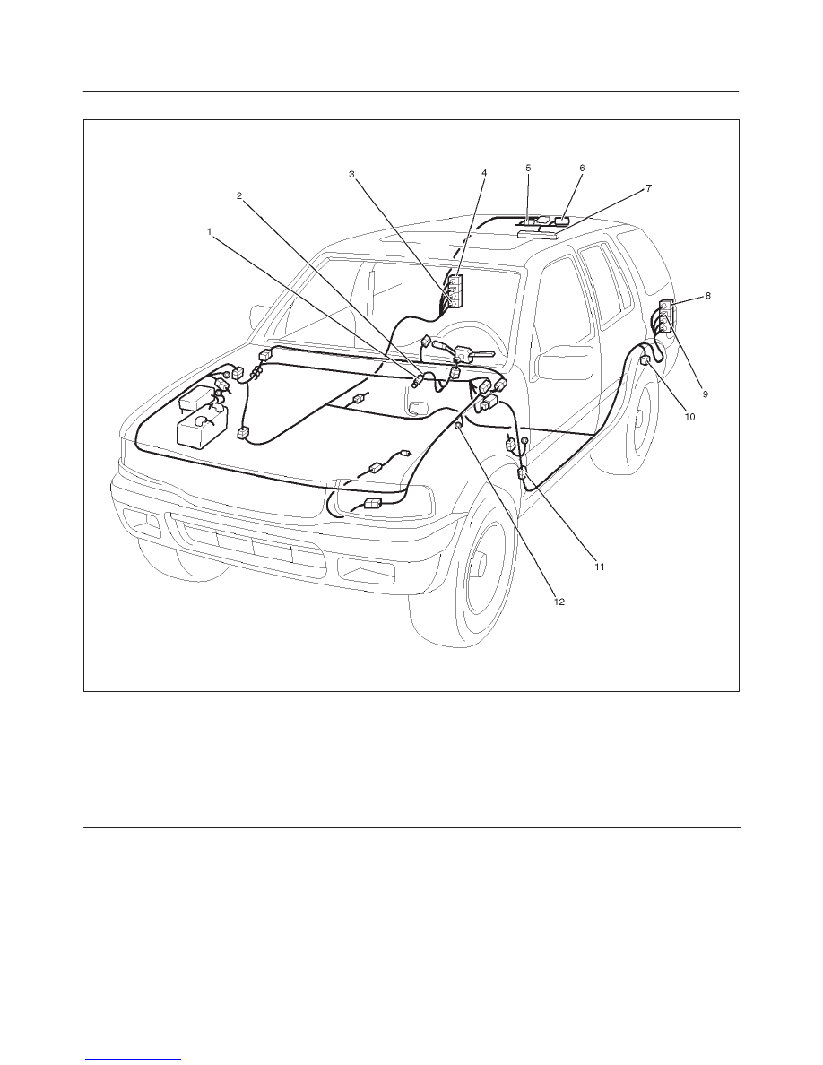
Parts Location
D08RW111
Legend
(1) Stop light SW
(2) I–18
(3) B–9
(4) Stop light – RH
(5) H–21
(6) G–10, G–11
(7) High Mounted Stop Light
(8) Stop light – LH
(9) B–13
(10) H–23
(11) H–32
(12) B–6, B–8