Isuzu Rodeo UE. Manual - part 550


  Index      Isuzu     Isuzu Rodeo UE - service repair manual 1999 year


Search            


Content   ..  548  549  550  551   ..


Isuzu Rodeo UE. Manual - part 550


8D–48

WIRING SYSTEM

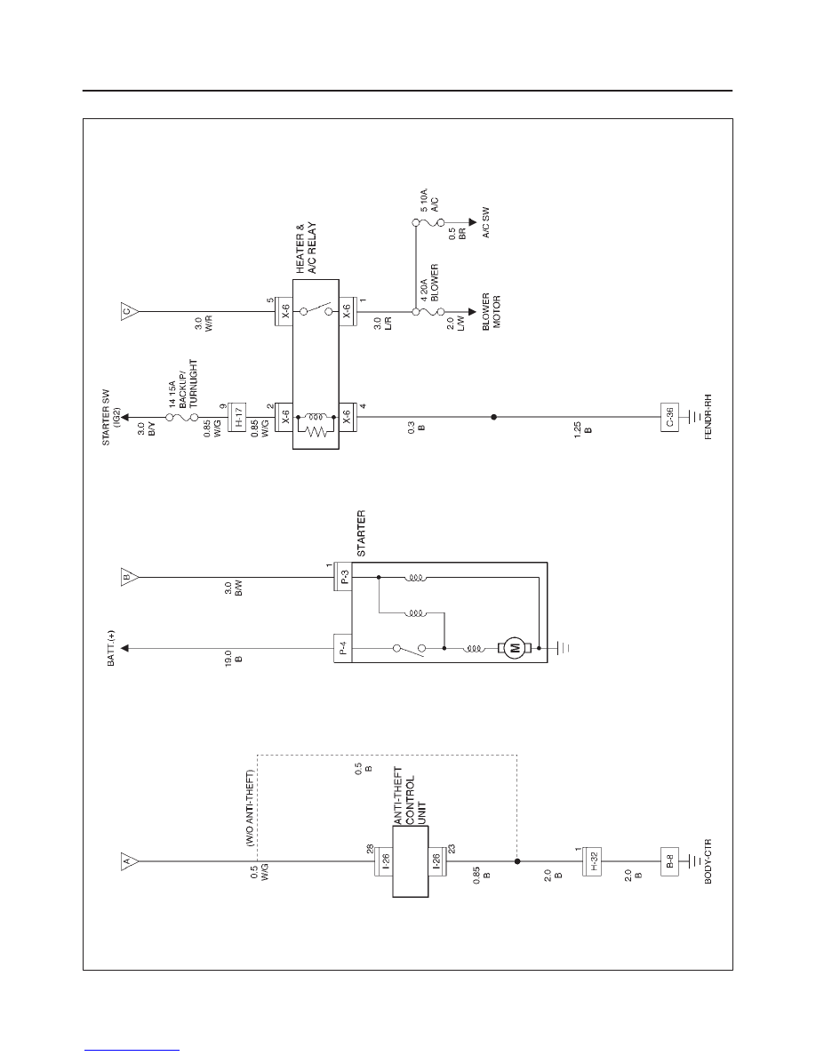
Circuit Diagram–3

D08RX016
8D–49

WIRING SYSTEM

Parts Location

D08RX017

Legend

(1) X–3, X–6
(2) H–2, H–3
(3) C–36
(4) H–13, H–14
(5) I–26
(6) B–8
(7) Starter Switch
(8) I–20 (M/T)
(9) H–17

(10) Mode Switch (A/T)

(11) M–16

(12) H–11
(13) P–4
(14) P–3
(15) P–8
(16) P–9
(17) P–7
(18) H–2

8D–50

WIRING SYSTEM

Powertrain Control Module (PCM)

General Description

The Powertrain Control Module (PCM) is located in the
passenger compartment.
The PCM constantly monitors the information from
various sensors, and controls the systems that affect
vehicle performance.
The PCM performs the diagnostic function of the system.
It can recognize operational problems, alert the driver
through the Malfunction Indicator Light (MIL) and store a
Diagnostic Trouble Code (DTC) or DTC(s) which identify
the problem areas to aid the technician in making repairs.
The PCM is designed to process the various input
informations and then send the necessary electrical
responses to control fuel delivery, spark timing and other
emission control systems. The input information has an
interrelation to more than one output therefore, if the one
input failed, it could affect more than one system
operation.
Refer to Driveability and Emission in Engine Section and
Automatic Transmission in Transmission section.

8D–51

WIRING SYSTEM

Circuit Diagram–1 (6VD1)

D08RX018


Content   ..  548  549  550  551   ..