Isuzu Rodeo UE. Manual - part 538
ENTERTAINMENT
8C–7
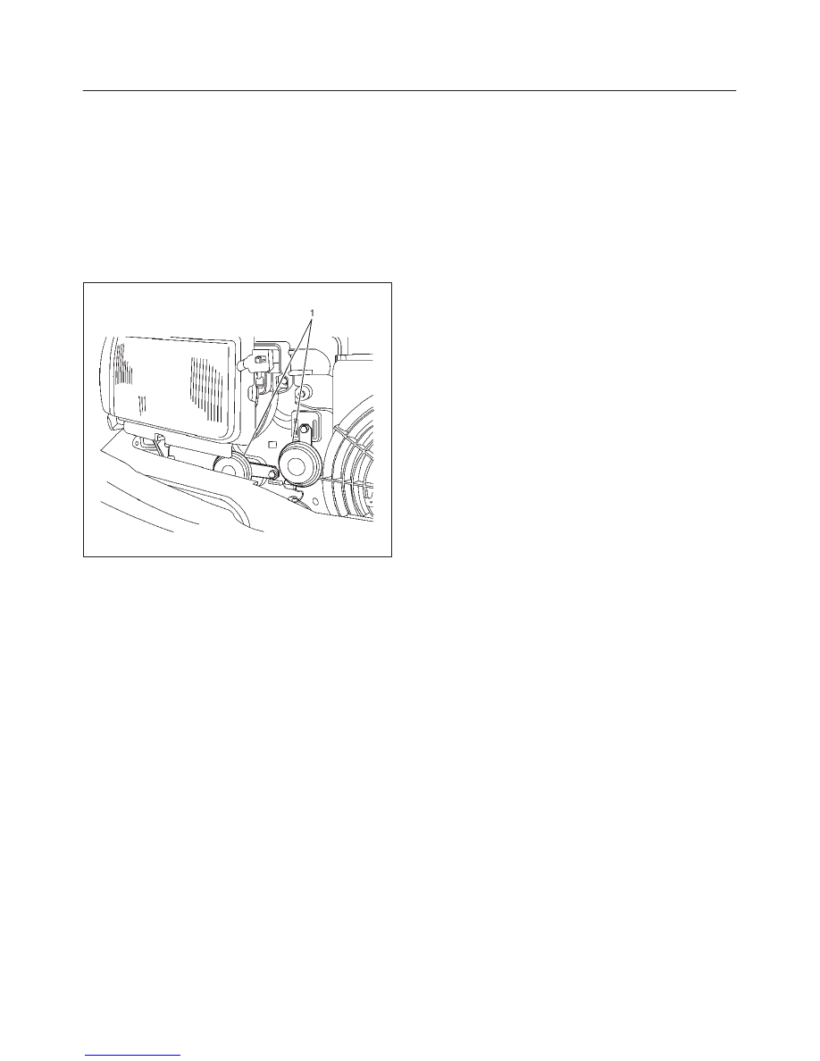
Horn
Removal
1. Disconnect the battery ground cable.
2. Remove the radiator grille.
f
Refer to Engine Hood and Fender in Body Structure
section.
3. Remove the horn (1).
f
Disconnect the connector.
f
Remove the horn mounting bolt.
828RX001
Installation
To install, follow the removal steps in the reverse order.