Isuzu Rodeo UE. Manual - part 524


  Index      Isuzu     Isuzu Rodeo UE - service repair manual 1999 year


Search            


Content   ..  522  523  524  525   ..


Isuzu Rodeo UE. Manual - part 524


CLUTCH

7C–19

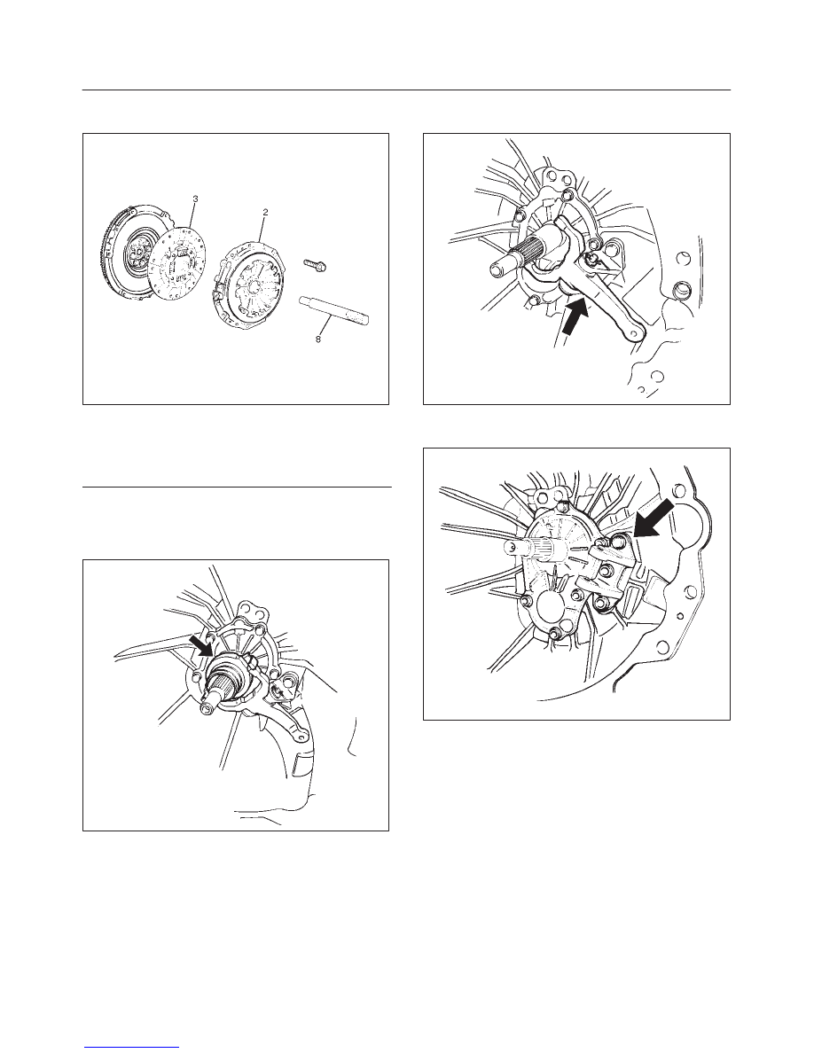
2. Use the pilot aligner J24547 to prevent the driven

plate assembly (3) from falling free.

201RS001

Legend

(2) Pressure Plate Assembly
(3) Driven Plate Assembly
(8) Pilot Aligner

3. Mark the flywheel, clutch cover and pressure plate lug

for alignment when installing.

4. Remove the release bearing (4) from the

transmission case.

201RS024

5. Remove the snap pin.  Remove the shift fork pin and

shift fork from the fulcrum bridge.

201RS025

6. Remove the fulcrum bridge bolts.  Remove the

fulcrum bridge (6) from the transmission case.

201RS026

7C–20

CLUTCH

f

Do not remove crankshaft bearing (7) except for
replacement.

f

Use the remover J–5822 and sliding hammer
J–23907 to remove the crankshaft bearing.

015RS045

Inspection and Repair

Make necessary correction or parts replacement if wear,
damage, or any other abnormal condition are found
through inspection.

Pressure Plate Assembly

f

Visually check the pressure plate friction surface for
excessive wear and heat cracks.  If excessive wear or
deep heat cracks are present, the pressure plate
must be replaced.

201RS002

Pressure Plate Warpage

f

Use a straight edge and a feeler gauge to measure
the pressure plate friction surface flatness in four
directions.  If any of the measured values exceed the
specified limit, the pressure plate must be replaced.

Pressure Plate Warpage

Limit: 0.3 mm (0.012 in)

201RS003

Clutch Cover

f

Visually check the entire clutch cover for excessive
wear, cracking, and other damage.   The clutch cover
must be replaced if any of these conditions are
present.

201RS004

CLUTCH

7C–21

Clutch Set Force

1. Invert the pressure plate assembly.
2. Place a new driven plate over the pressure plate.  A

metal sheet with thickness of 8.0mm (0.315in) may
be used in place of the driven plate.

3. Compress the pressure plate assembly until the

distance becomes 12mm (0.472in).

4. Note the pressure gauge reading.  If the measured

value is less than the specified limit, the pressure
plate assembly must be replaced.

Clutch Set Force
Standard: 7208N (1621lb)
Limit: 6669N (1499lb)

201RW014

Diaphragm Spring Finger Height

1. Place a new driven plate or a 8.0mm (0.315in) spacer

beneath the pressure plate.

2. Fully compress the pressure plate and diaphragm

spring.
There are two ways to do this:

a. Use a bench press to press down on the assembly

from the top.

b. Tighten the fixing bolts.

NOTE: Preload on diaphragm spring finger must be
4998N (11-22lb) in direction of release, when clutch
cover assembly is bolted to the flywheel.

3. Measure the spring height from base to spring tip. If

the measured value exceeds the specified limit, the
pressure plate assembly must be replaced.

Spring Finger Height

Standard: 49.9 – 51.9 mm (1.965– 2.043 in)

201RW016

Driven Plate Assembly

f

Visually check the torsion spring for looseness,
breakage, and weakening. If any of these conditions
are discovered, the driven plate assembly must be
replaced.

f

Visually check the facing surfaces for cracking and
excessive scorching.  Visually inspect the facing
surfaces for the presence of oil or grease.  If any of
these conditions are discovered, the facing must be
cleaned or replaced.

f

Check that the driven plate moves smoothly on the
transmission top gear shaft spline.  Minor ridges on
the top gear shaft spline may be removed with an oil
stone.

201RS007

7C–22

CLUTCH

Driven Plate Warpage

1. Insert the clutch pilot aligner J–24547 into the driven

plate splined hub.  The clutch pilot aligner must be
held perfectly horizontal.

2. Set a dial indicator to the driven plate outside

circumference.

3. Slowly turn the driven plate.  Read the dial indicator as

you turn the driven plate.  If the measured value
exceeds the specified limit, the driven plate assembly
must be replaced.

Driven Plate Warpage
Standard: 0.7mm (0.028in)
Limit: 1.0mm (0.039in)

201RS008

Driven Plate Splined Hub Spline Wear

1. Clean the driven plate splined hub.
2. Install the driven plate to the transmission top gear

shaft spline.

3. Set a surface gauge to the driven plate outside

circumference.

4. Slowly turn the driven plate counterclockwise.

Measure the spline rotation play as you turn the
driven plate.  If the measured value exceeds the
specified limit, the driven plate assembly must be
replaced.

Driven Plate Warpage
Standard: 0.5mm (0.020in)
Limit: 1.0mm (0.039in)

201RS009

Rivet Head Depression

f

Use a depth gauge or a straight edge with steel rule to
measure the rivet head depression (1) from the facing
surface (2).

f

Be sure to measure the rivet head depression on both
sides of the driven plate.  If the measured value is less
than the specified limit, the driven plate assembly
must be replaced.

Rivet Head Depression

Standard

Limit

Fly wheel side

1.2–1.8mm

(0.047–0.071in)

0.2mm

Pressure plate
side

1.6–2.2mm

(0.062–0.087in)

(0.008in)

201RS010


Content   ..  522  523  524  525   ..