Isuzu Rodeo UE. Manual - part 458
7A–48
AUTOMATIC TRANSMISSION (4L30–E)
Powertrain Control Module (PCM)
Removal
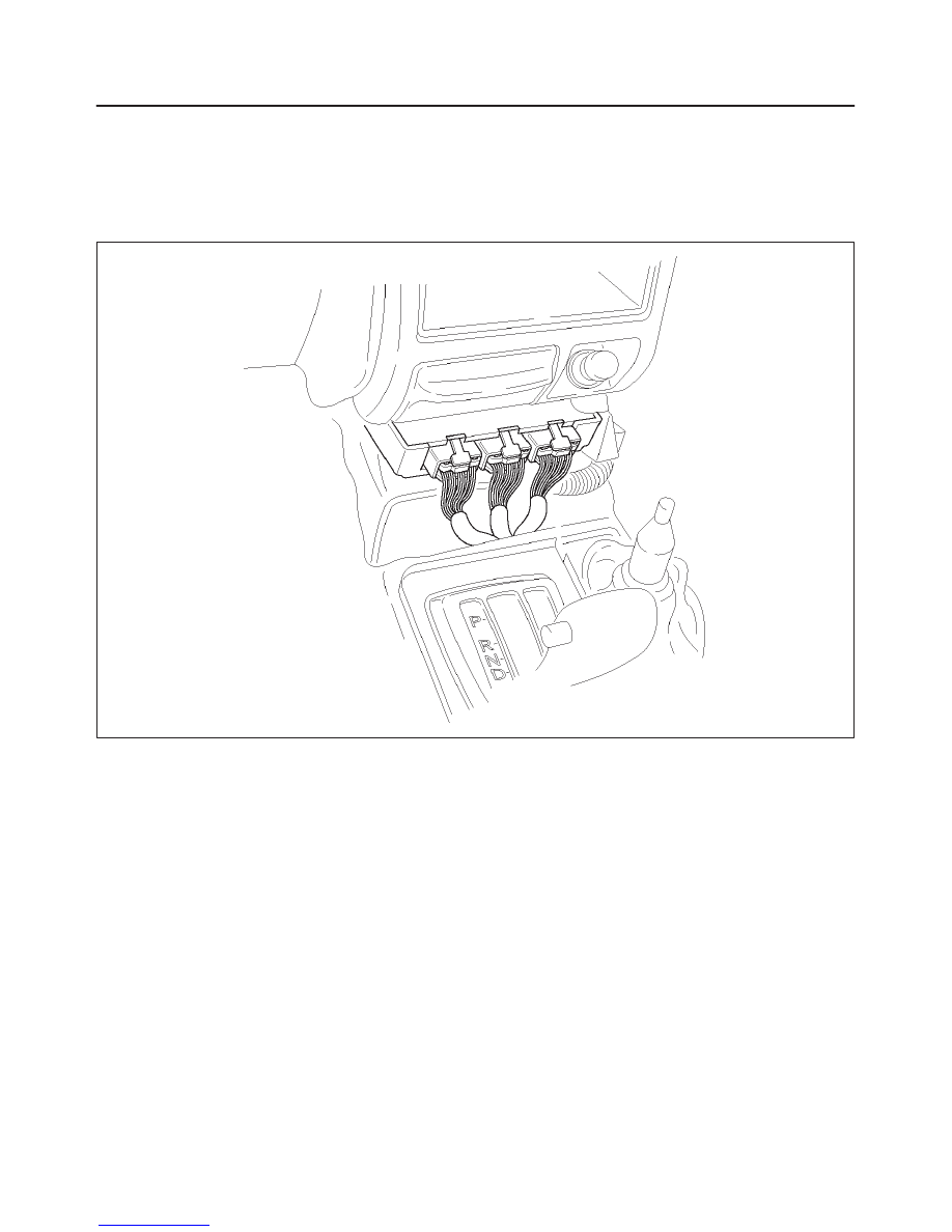
1. Disconnect battery ground cable.
2. Remove transfer control lever knob, lower cluster
assembly, center console and front console.
3. Disconnect PCM wiring harness connectors from
PCM.
4. Remove four PCM retaining screws.
5. Remove two brackets from PCM.
828RW003
Installation
1. Install two brackets to PCM.
2. Install four PCM retaining screws.
3. Connect PCM wiring harness connectors to PCM.
4. Install center console, rear console, lower cluster
assembly and transfer control lever knob.
5. Connect battery ground cable.