Isuzu Rodeo UE. Manual - part 328


  Index      Isuzu     Isuzu Rodeo UE - service repair manual 1999 year


Search            


Content   ..  326  327  328  329   ..


Isuzu Rodeo UE. Manual - part 328


6E2–67

RODEO 6VD1 3.2L ENGINE DRIVEABILITY AND EMISSIONS

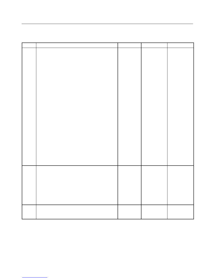
Injector Coil Test Procedure (Steps 1-6) and Injector Balance Test Procedure

(Steps 7-11)

  (Cont'd)

Step

No

Yes

Value(s)

Action

9

1. Connect the J 39021-5V Fuel Injector Tester and J

39021-90 Injector Switch Box the fuel injector
harness connector.

2. Set the amperage supply selector switch on the fuel

injector tester to the “Balance Test” 0.5-2.5 amp
position.

3. Using the Tech 2 turn the fuel pump “ON” then

“OFF” in order to pressurize the fuel system.

4. Record the fuel pressure indicated by the fuel

pressure gauge after the fuel pressure stabilizes.
This is the first pressure reading.

5. Energize the fuel injector by depressing the “Push

to Start Test” button on the fuel injector tester.

6. Record the fuel pressure indicated by the fuel

pressure gauge after the fuel pressure gauge
needle has stopped moving.  This is the second
pressure reading.

7. Repeat steps 1 through 6 for each fuel injector.
8. Subtract the second pressure reading from the first

pressure reading for one fuel injector.  The result is
the pressure drop value.

9. Obtain a pressure drop value for each fuel injector.
10.Add all of the individual pressure drop values.  This

is the total pressure drop.

11. Divide the total pressure drop by the number of fuel

injectors.  This is the average pressure drop.

Does any fuel injector have a pressure drop value that
is either higher than the average pressure drop or lower
than the average pressure drop by the specified value?

10 kPa (1.5

psi)

Go to 

Step 10

Go to 

OBD

System

Check

10

Re-test any fuel injector that does not meet the
specification. Refer to the procedure in step 9.

NOTE: Do not repeat any portion of this test before
running the engine in order to prevent the engine from
flooding.

Does any fuel injector still have a pressure drop value
that is either higher than the average pressure drop or
lower than the average pressure drop by the specified
value?

10 kPa (1.5

psi)

Go to 

Step 11

Go to

Symptoms

11

Replace the faulty fuel injector(s).  Refer to 

Fuel

Injector.

Is the action complete?

Verify repair

6E2–68

RODEO 6VD1 3.2L ENGINE DRIVEABILITY AND EMISSIONS

Knock Sensor Diagnosis

The Tech 2 has two data displays available for diagnosing
the knock sensor (KS) system.  The two displays are
described as follows:

f

“Knock Retard” indicates the number of degrees that
the spark timing is being retarded due to a knock
condition.

f

“KS Noise Channel” indicates the current voltage
level being monitored on the noise channel.

DTCs P0325 and P0327 are designed to diagnose the KS
module, the knock sensor, and the related wiring.  The
problems encountered with the KS system should set a
DTC. However, if no DTC was set but the KS system is
suspect because of a detonation complaint, refer to
Detonation/Spark Knock in Symptoms.

Powertrain Control Module (PCM)

Diagnosis

To read and clear diagnostic trouble codes, use a Tech 2.
IMPORTANT:

Use of a Tech 2 is recommended to clear

diagnostic trouble codes from the PCM memory.
Diagnostic trouble codes can also be cleared by turning
the ignition “OFF” and disconnecting the battery power
from the PCM for 30 seconds.  Turning off the ignition and
disconnecting the battery power from the PCM will cause
all diagnostic information in the PCM memory to be
cleared.  Therefore, all the diagnostic tests will have to be
re-run.
Since the PCM can have a failure which may affect only
one circuit, following the diagnostic procedures in this
section will determine which circuit has a problem and
where it is.
If a diagnostic chart indicates that the PCM connections
or the PCM is the cause of a problem, and the PCM is
replaced, but this does not correct the problem, one of the
following may be the reason:

f

There is a problem with the PCM terminal
connections.  The terminals may have to be removed
from the connector in order to check them properly.

f

EEPROM program is not correct for the application.
Incorrect components or reprogramming the PCM
with the wrong EEPROM program may cause a
malfunction and may or may not set a DTC.

f

The problem is intermittent.  This means that the
problem is not present at the time the system is being
checked.  In this case, refer to the 

Symptoms portion

of the manual and make a careful physical inspection
of  all components and wiring associated with the
affected system.

f

There is a shorted solenoid, relay coil, or harness.
Solenoids and relays are turned “ON” and “OFF” by
the PCM using internal electronic switches called
drivers.  A shorted solenoid, relay coil, or harness will
not damage the PCM but will cause the solenoid or
relay to be inoperative.

Multiple PCM Information Sensor

DTCS Set

Circuit Description

The powertrain control module (PCM) monitors various
sensors to determine the engine operating conditions.
The PCM controls fuel delivery, spark advance,
transmission operation, and emission control device
operation based on the sensor inputs.
The PCM provides a sensor ground to all of the sensors.
The PCM applies 5 volts through a pull-up resistor, and
determines the status of the following sensors by
monitoring the voltage present between the 5-volt supply
and the resistor:

f

The engine coolant temperature (ETC) sensor

f

The intake air temperature (IAT) sensor

f

The transmission fluid temperature (TFT) sensor

The PCM provides the following sensors with a 5-volt
reference and a sensor ground signal:

f

The exhaust gas recirculating (EGR) pintle position
sensor

f

The throttle position (TP) sensor

f

The manifold absolute pressure (MAP) sensor

The PCM monitors the separate feedback signals from
these sensors in order to determine their operating
status.

Diagnostic Aids

IMPORTANT:

Be sure to inspect PCM and engine

grounds for being secure and clean.
A short to voltage in one of the sensor input circuits may
cause one or more of the following DTCs to be set:

f

P0108/P1106

f

P0113/P1111

f

P0118/P1115

f

P0123/P1121

f

P0560

f

P0712

IMPORTANT:

If a sensor input circuit has been shorted

to voltage, ensure that the sensor is not damaged. A
damaged sensor will continue to indicate a high or low
voltage after the affected circuit has been repaired.  If the
sensor has been damaged, replace it.
An open in the sensor ground circuit between the PCM
and the splice will cause one or more of the following
DTCs to be set:

f

P0108/P1106

f

P0113/P1111

f

P0118/P1115

f

P0123/P1121

f

P0712

A short to ground in the 5-volt reference A or B circuit will
cause one or more of the following DTCs to be set:

f

P0107/P1107

f

P0122/P1122

f

P1406

6E2–69

RODEO 6VD1 3.2L ENGINE DRIVEABILITY AND EMISSIONS

An the in the 5-volt reference circuit A, between the PCM
and the splice will cause one or more of the following
DTCs to be set:

f

P0122/P1122

f

P1406

An the in the 5-volt reference circuit B, between the PCM
and the splice will cause one or more of the following
DTCs to be set:

f

P0107/P1107

Check for the following conditions:

f

Poor connection at PCM. Inspect the harness
connectors for backed-out terminals, improper
mating, broken locks, improperly formed or damage
terminals, and a poor terminal-to-wire connection.

f

Damaged harness. Inspect the wiring harness for
damage.  If the harness is not damaged, observe an
affected sensor’s displayed value on the Tech 2 with
the ignition “ON” and the engine “OFF” while you
move the connectors and the wiring harnesses
related to the following sensors:

f

IAT

f

ECT

f

TP

f

MAP

f

EGR

f

TFT

Test Description

9. A faulty EGR valve can leak a small amount of

current from the ignition feed circuit to the 5-volt
reference A circuit.  If the problem does not exist
with the EGR valve disconnected, replace the EGR
valve.

11-15. If a sensor input circuit has been shorted to

voltage, ensure that the sensor has not been
damaged.  A damaged IAT or ECT sensor will
continue to indicate a high voltage or a low
temperature after the affected circuit has been
repaired.  A dameged TP, MAP, fuel tank pressure,
or EGR pintle position sensor will indicate a high
voltage, a low voltage, or a fixed value after the
affected circuit has been repaired.  If the sensor has
been damaged, replace it.

Multiple PCM Information Sensor DTCs Set


Step

Action

Value(s)

Yes

No

1

Was the “On-Board Diagnostic (OBD) System Check”
performed?

Go to 

Step 2

Go to 

OBD

System

Check

2

1. Turn the ignition “OFF,” disconnect the PCM.
2. Turn the ignition “ON,” check the 5 volt reference A

circuit for the following conditions:

f

A poor connection at the PCM.

f

An open between the PCM connector and the
splice.

f

A short to ground.

f

A short to voltage.

Is there an open or short?

Go to 

Step 3

Go to 

Step 4

3

Repair the open or short.

Is the action complete?

Verify repair

4

Check the sensor ground circuit for the following
conditions:

f

A poor connection at the PCM or the affected
sensors.

f

An open between the PCM connector and the
affected sensors.

Is there an open or a poor connection?

Go to 

Step 5

Go to 

Step 6

5

Repair the open or the poor connection.

Is the action complete?

Verify repair

6

Measure the voltage between the EGR pintle position
sensor signal circuit at the PCM harness connector and
ground.

Does the voltage measure near the specified value?

0 V

Go to 

Step 7

Go to 

Step 11

6E2–70

RODEO 6VD1 3.2L ENGINE DRIVEABILITY AND EMISSIONS

Multiple PCM Information Sensor DTCs Set

  (Cont'd)

Step

No

Yes

Value(s)

Action

7

Measure the voltage between the MAP sensor signal
circuit at the PCM harness connector and ground.

Does the voltage measure near the specified value?

0 V

Go to 

Step 8

Go to 

Step 14

8

Measure the voltage between the TP sensor signal
circuit at the PCM harness connector and ground.

Does the voltage measure near the specified value?

0 V

Go to 

Step 9

Go to 

Step 15

9

Measure the voltage between the IAT sensor signal
circuit at the PCM harness connector and ground.

Does the voltage measure near the specified value?

0 V

Go to 

Step 10

Go to 

Step 16

10

Measure the voltage between the ECT sensor signal
circuit at the PCM harness connector and ground.

Does the voltage measure near the specified value?

0 V

Go to 

Step 11

Go to 

Step 17

11

1. Disconnect the EGR valve.
2. Measure the voltage between the EGR pintle

position sensor signal circuit at the PCM harness
connector and ground.

Does the voltage measure near the specified value?

0 V

Go to 

Step 13

Go to 

Step 18

12

Measure the voltage between the TFT sensor signal
circuit at the PCM harness connector and ground.

Does the voltage measure near the specified value?

0 V

Go to 

Step 20

Go to 

Step 19

13

Replace the EGR valve.

Is the action complete?

Verify repair

14

Locate and repair the short to voltage in the MAP
sensor signal circuit.

Is the action complete?

Verify repair

15

Locate and repair the short to voltage in the TP sensor
signal circuit.

Is the action complete?

Verify repair

16

Locate and repair the short to voltage in the IAT sensor
signal circuit.

Is the action complete?

Verify repair

17

Locate and repair the short to voltage in the ECT
sensor signal circuit.

Is the action complete?

Verify repair

18

Locate and repair the short to voltage in the EGR pintle
position sensor signal circuit.

Is the action complete?

Verify repair


Content   ..  326  327  328  329   ..