Isuzu Rodeo UE. Manual - part 284


  Index      Isuzu     Isuzu Rodeo UE - service repair manual 1999 year


Search            


Content   ..  282  283  284  285   ..


Isuzu Rodeo UE. Manual - part 284


6A–49

ENGINE MECHANICAL (6VD1 3.2L)

10. Install power steering pump, tighten fixing bolt to the

specified torque.

Torque :
M8 bolts : 22N·m (16 lb ft)
M10 bolts : 46 N·m (34 lb ft)

11. Move drive belt tensioner to loose side using wrench,

then install drive belt to normal position.
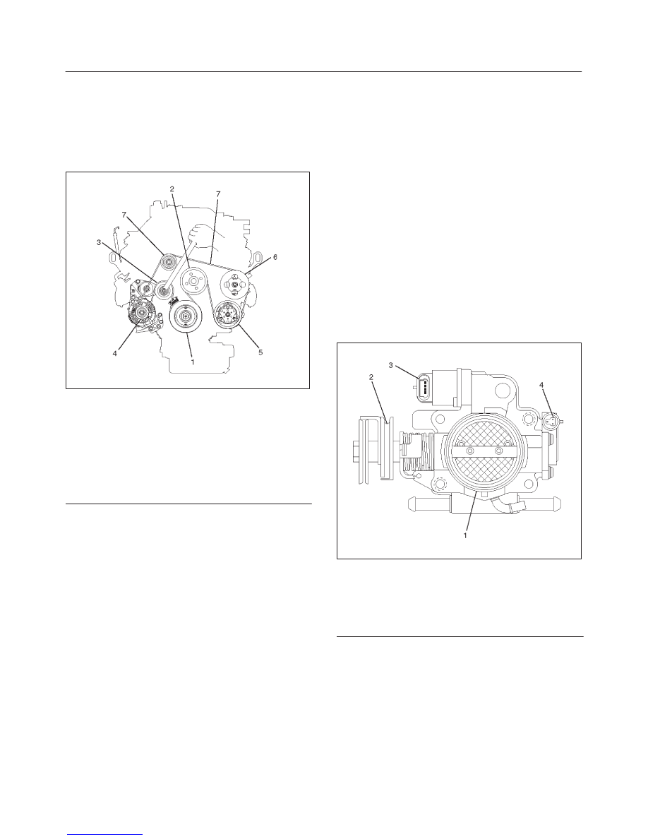
850RW001

Legend

(1) Crankshaft Pulley
(2) Cooling Fan Pulley
(3) Tensioner
(4) Generator
(5) Air Conditioner Compressor
(6) Power Steering Oil Pump
(7) Drive Belt

12. Install upper fan shroud.
13. Reconnect radiator upper and lower hoses.
14. Reconnect coolant reserve tank hose to radiator.
15. Reconnect generator harness connector.
16. Reconnect starter harness connector.
17. Reconnect bonding cable terminal on left bank
18. Reconnect bonding cable terminal on the back of right

dash panel.

19. Reconnect ground cable between engine and

chassis.

20. Reconnect harness connector to transmission and

install transmission harness bracket on engine left
side.

21. Reconnect three engine harness connectors.
22. Reconnect vacuum booster hose.
23. Reconnect canister vacuum hose.
24. Install air cleaner assembly.
25. Reconnect air duct.
26. Reconnect accelerator cable and automatic cruise

control cable to throttle valve on common chamber.

035RW007

Legend

(1) Throttle Valve Assembly
(2) Throttle Lever
(3) Idle Air Control Valve
(4) Throttle Position Sensor

6A–50

ENGINE MECHANICAL (6VD1 3.2L)

27. Install engine hood to the original position.

f

Refer to installation procedure for Body section in
this manual.

28. Install Accelerator pedal cable.

6A–51

ENGINE MECHANICAL (6VD1 3.2L)

Cylinder Head

Cylinder Head and Associated Parts

011RW008

Legend

(1) Spark Plug
(2) Cylinder Head Bolt
(3) Camshaft Drive Gear Pulley Fixing Bolt
(4) Camshaft Drive Gear Pulley
(5) Camshaft Bracket Fixing Bolt
(6) Camshaft Bracket
(7) Camshaft Exhaust

(8) Camshaft Intake
(9) Retainer Fixing Bolt

(10) Retainer Assembly

(11) Tappet with Shim

(12) Split Collar
(13) Valve Spring and Spring Upper Seat
(14) Valve

Disassembly

NOTE:

f

During disassembly, be sure that the valve train
components are kept together and identified so that
they can be reinstalled in their original locations.

f

Before removing the cylinder head from the engine
and before disassembling the valve mechanism,
perform a compression test and note the results.

1. Remove camshaft drive gear pulley fixing bolt (3),

then pulley (4).

6A–52

ENGINE MECHANICAL (6VD1 3.2L)

2. Remove camshaft bracket fixing bolt (5), camshaft

bracket (6), then camshaft exhaust (7), and intake
side (8).

3. Remove tappet with shim (11).
4. Use the J–8062 valve spring compressor and

J–42898 valve spring compressor adapter to remove
the split collar (12), valve spring with upper seat (13)
and valve (14).

014RW042

5. Remove spark plug (1).

CAUTION: Do not remove the spark plugs when the
head and plugs are hot. Clean dirt and debris from
spark plug recess areas before removal.

Clean

Cylinder head

Carefully remove all varnish, soot and carbon from the
bare metal. Do not use a motorized wire brush on any
gasket sealing surface.

Inspection and Repair

1. Cylinder head gasket and mating surfaces for leaks,

corrosion and blow–by. If the gasket has failed,
determine the cause.
– Insufficient torque on head bolts
– Improper installation
– Loose or warped cylinder head
– Missing dowel pins
– Warped case surface

2. Cylinder head for cracks, especially between valve

seats and in the exhaust ports.

3. Cylinder head deck for corrosion, sand particles in

head and porosity.

CAUTION:

f

Do not attempt to weld the cylinder head. Replace
it.

f

Do not reuse cylinder head bolts.

4. Cylinder head deck, common chamber and exhaust

manifold mating surfaces for flatness. These
surfaces may be reconditioned by milling. If the
surfaces are “out of flat” by more than specification,
the surface should be ground to within specifications.
Replace the head if it requires machining beyound the
repairable limit.

Head surface and manifold surface
Standard: 0.05 mm (0.002 in) or less
Warpage limit: 0.2 mm (0.0079 in)
Maximum Repairable limit: 0.2 mm (0.0079 in)

Head height
Standard height : 133.2 mm (5.2441 in)
Warpage limit : 0.2 mm (0.0079 in)
Maximum Repairable limit : 133.0 mm (5.2362 in)

011RW019

5. Water jacket sealing plugs seating surfaces.


Content   ..  282  283  284  285   ..