Isuzu Rodeo UE. Manual - part 67
DIFFERENTIAL (REAR)
4A2–33
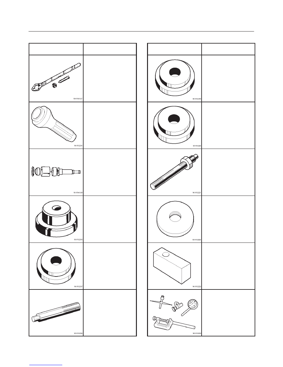
Special Tools
ILLUSTRATION
TOOL NO.
TOOL NAME
J–8614–01
Pinion flange holder
J–37263
Installer; Pinion oil seal
J–42379
Remover; Bearing
J–39830
Adapter; Side bearing
plug
J–8611–01
Installer; Outer bearing
outer race
J–8592
Grip
ILLUSTRATION
TOOL NO.
TOOL NAME
J–42836
Installer; Inner bearing
outer race
J–42824
Pilot;Outer
J–21777–43
Nut & Stud
J–42827
Pilot;Inner
J–39837–2
Gauge plate
J–8001
Dial indicator