Isuzu Rodeo UE. Manual - part 65


  Index      Isuzu     Isuzu Rodeo UE - service repair manual 1999 year


Search            


Content   ..  63  64  65  66   ..


Isuzu Rodeo UE. Manual - part 65


DIFFERENTIAL (REAR)

4A2–25

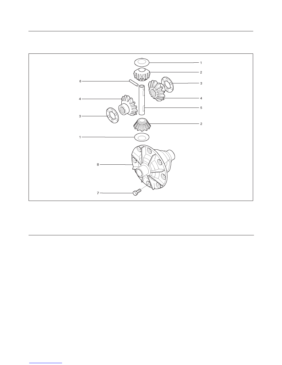
Differential Case Assembly

Disassembled View

425RW014

Legend

(1) Thrust Washer (for Pinion Gear)
(2) Pinion Mate Gear
(3) Thrust Washer(for Side Gear)
(4) Side Gear

(5) Differential Shaft
(6) Lock Pin
(7) Bolt
(8) Differential Case

4A2–26

DIFFERNTIAL (REAR)

Disassembly

1. Remove lock pin using a small drift.

425RS098

2. Remove the differential shaft by using a soft metal rod

and a hammer.

425RS043

3. Remove pinion mate gear and thrust washer.
4. Remove side gear and thrust washer.

Inspection and Repair

Make necessary correction or parts replacement if wear,
damage, corrosion or any other abnormal condition are
found through inspection.
Check the following parts.

f

Ring gear, pinion gear

f

Bearing

f

Side gear, pinion mate gear, differential shaft

f

Differential case, carrier

f

Thrust washer

f

Oil seal

Reassembly

1. Install side gear with thrust washer.
2. Install the pinion mate gear with thrust washer by

engaging it with the side gears while turning both
pinion mate gears simultaneously in the same
direction.

425RS048

3. Install differential shaft.

1. Be sure to install the differential shaft so that it is in

alignment with the lock pin hole in the differential
case.

425RS049

4. Install lock pin.

After lock pin installation, stake the case to secure the
lock pin.

DIFFERENTIAL (REAR)

4A2–27

Limited Slip Differential Assembly

Disassembled View

425RW004

Legend

(1) Thrust Washer–Differential Pinion Mate Gear
(2) Pinion Mate Gear
(3) Dished Spacer
(4) Disc
(5) Plate

(6) Differential Plate Retainer
(7) Lock Pin
(8) Differential Case
(9) Ring Gear Bolts

(10) Differential Shaft

(11) Differential Side Gear

Disassembly

1. Place the holder J–39824 into a vise.

Position the differential on the holder with the ring
gear side down.

2. Remove Lock pin (1) from differential shaft using a

punch.

3. Remove Differential shaft (2) using hammer and

punch.
Place shop towel behind case to prevent differential
shaft from dropping out of case.

425RW005

4A2–28

DIFFERNTIAL (REAR)

4. Assemble clutch pack unloading tool .

a. Install cap J–34174–1 to the bottom differential

side gear.

b. Install threaded screw cap J–34174–2 to top

differential side gear. Thread forcing screws
J–22342–15 into threaded screw cap until it
becomes centered into the bottom cap.

901RW153

c. Tighten forcing screw until tight enough to collapse

dished spacers and and allow looseness between
side and pinion mate gears.

5. Both pinion mate gear thrust washers using a shim

stock (1) of 0.51 mm (0.020 in.) or equivalent tool to
push out washers.

425RW007

6. Relieve tension of dished spacers by loosening

forcing screw.

NOTE:

f

You may have to adjust the forcing screw slightly to
allow the case to rotate.

7. Assemble LSD service adapter J–39834 onto long

drive handle J–8592.Insert it into differential shaft
hole of case. Pull on handle and rotate case until
pinion mate gears can be removed.

901RW068

8. Remove pinion mate gears.
9. Hold side gear top clutch pack (1) with one hand and

remove positraction unloading tools.

425RW008

10. Remove top side gear and clutch pack.

NOTE:

f

Keep the stack of plates and discs intact and in
exactly the same position while they are being
removed.

11. Remove case from holder.  Turn case with flange or

ring gear side up to allow side gear and clutch pack to
be removed from case.


Content   ..  63  64  65  66   ..