Isuzu Rodeo UE. Manual - part 41


  Index      Isuzu     Isuzu Rodeo UE - service repair manual 1999 year


Search            


Content   ..  39  40  41  42   ..


Isuzu Rodeo UE. Manual - part 41


FRONT SUSPENSION

3C–11

9. Remove back plate.

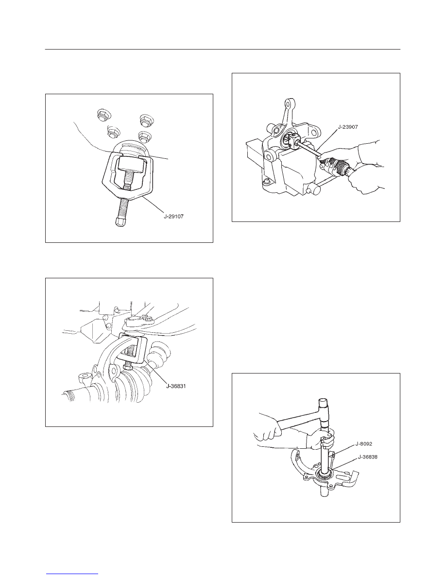
10. Remove lower ball joint by using remover J–29107.

CAUTION: Be careful not to damage the ball joint
boot.

901RW163

11. Remove upper ball joint by using remover J–36831.

CAUTION: Be careful not to damage the ball joint
boot.

901RW162

12. Remove knuckle assembly.
13. Remove oil seal (Except 2WD model).
14. Remove washer (Except 2WD model).

15. Remove needle bearing by using remover J–23907

(Except 2WD model).

901RW044

Inspection and Repair

Make necessary correction or parts replacement if wear,
damage, corrosion or any other abnormal condition are
found through inspection.
Check the following parts:

f

Knuckle

f

Knuckle arm

f

Needle bearing

f

Thrust washer

Installation

1. Apply appropriate amount of multipurpose type

grease to the new bearing (Approx. 5 g) and install
needle bearing by using installer J–36838 and
J–8092 (Except 2WD model).

901RW045

3C–12

FRONT SUSPENSION

2. Apply multipurpose type grease to the thrust washer,

and install washer with chamfered side facing knuckle
(Except 2WD model). 

3. Use a new oil seal, and apply multipurpose type

grease to the area surrounded by the lip (approx. 2 g).
Then use installer J–36837 and J–8092 to install oil
seal.  After fitting the oil seal to the installer, drive it to
the knuckle using a hammer or bench press until the
tool front face contacts with the thrust washer (Except
2WD model).

901RW167

4. Install knuckle assembly.
5. Install upper ball joint and tighten the nut to the

specified torque, with just enough additional torque to
align cotter pin holes. Install new cotter pin.

Torque: 98 N·m (72 lb ft)

6. Install lower ball joint and tighten the nut to the

specified torque, with just enough additional torque to
align cotter pin holes. Install new cotter pin.

Torque: 147 N·m (108 lb ft)

7. Install back plate.
8. Install wheel speed sensor.
9. Install torsion bar, refer to Torsion Bar in this section. 

NOTE: Adjust the trim height. Refer to Front End
Alignment Inspection and Adjustment  in Steering.

FRONT SUSPENSION

3C–13

Upper Control Arm

Upper Control Arm and Associated Parts

450RW005

Legend

(1) Bolt and Plate
(2) Camber Shims
(3) Caster Shims
(4) Nut Assembly
(5) Upper Control Arm Assembly
(6) Fulcrum Pin

(7) Bushing
(8) Plate
(9) Nut

(10) Speed Sensor Cable

(11) Nut and Cotter Pin

(12) Upper Ball Joint

Removal

1. Raise the vehicle and support the frame with suitable

safety stands.

2. Remove wheel and tire assembly. Refer to Wheel in

this section.

3. Remove the brake caliper and disconnect brake pipe.

Refer to Disc Brakes in Brake section.

4. Support lower control arm with a jack. 
5. Remove speed sensor cable.
6. Remove nut and cotter pin then use remover

J–36831.

3C–14

FRONT SUSPENSION

CAUTION: Be careful not to damage the ball joint
boot.

901RW162

7. Remove upper ball joint.
8. Remove bolt and plate.
9. Remove nut assembly.

10. Remove camber shims and note the positions and

number of shims.

11. Remove caster shims and note the positions and

number of shims.

12. Remove upper control arm assembly.
13. Remove nut.
14. Remove plate.
15. Remove bushing by using remover J–29755.

901RW161

901RW160

16. Remove fulcrum pin.

Inspection and Repair

Make necessary parts replacement if wear, damage,
corrosion or any other abnormal conditions are found
through inspection.
Check the following parts:

f

Upper control arm

f

Bushing

f

Fulcrum pin 

Installation

1. Install fulcrum pin.
2. Install bushing by using installer J–29755 and

J–39376.

901RW164


Content   ..  39  40  41  42   ..