Isuzu KB P190. Manual - part 347


  Index      Isuzu     Isuzu KB P190 - service repair manual 2007 year


Search            


Content   ..  345  346  347  348   ..


Isuzu KB P190. Manual - part 347


6A-28  ENGINE MECHANICAL (4JK1/4JJ1) 

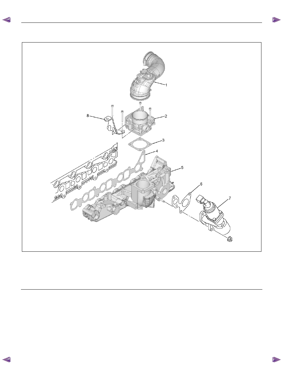
Components (High Output) 


RTW76ALF000301 

Legend 

 1. Intake 

Duct 

 2. Intake 

Throttle 

  3.  Intake Throttle Gasket 

  4.  Intake Manifold Gasket 


5. 

Intake 

Manifold 

  6.  EGR Valve Assembly Gasket 

  7.  EGR Valve Assembly 

 8. Bracket 


ENGINE MECHANICAL (4JK1/4JJ1)  6A-29 

Removal 

1.  Remove the engine cover. 

2.  Disconnect the connectors. 

• Fuel 

Injector 

• Throttle 

Assembly 

• EGR 

Valve 

• Glow 

Plug 

• Barometric 

Sensor 

•  A/C Compressor Connector 

3.  Remove the A/C belt 

4.  Remove the A/C compressor. 

5.  Remove the A/C compressor bracket. 

6.  Remove the intake air duct (Standard output). 


RTW56ASH024801

Legend 

  1.  A/C Compressor Bracket 

  2.  Intake Air Duct 

 3. A/C 

Compressor 


7.  Remove the intercooler (High output). 

• Disconnect the BARO sensor harness

connector (2). 

•  Remove the two intake hoses. 
•  Remove the intercooler (1). 


RTW76ASH000501

8.  Remove the injector leak-off hose (1). 


RTW56ASH024301

9.  Remove the engine oil level gauge guide tube. 

10. Remove the EGR valve. 


6A-30  ENGINE MECHANICAL (4JK1/4JJ1) 


RTW66ASH003001

11. Remove the injection pipes. 

•  Remove sequentially from No.1 cylinder. 

12. Disconnect the vacuum hose of swirl control valve

(1). 


RTW66ASH003101

13. Remove the throttle assembly and gasket. 


RTW56ASH005201

Legend 

 1. Throttle 

Assembly 

 2. Intake 

Manifold 


14. Remove the intake manifold. 


RTW56ASH018001

15. Remove the intake manifold gasket. 


ENGINE MECHANICAL (4JK1/4JJ1)  6A-31 

Installation 

1.  Install the intake manifold gasket. 

2.  Install the intake manifold. 

• Tighten the nuts and bolts in the order

described in the drawing. 

Tightening torque: 25 N

⋅⋅⋅⋅m (2.5 kg⋅⋅⋅⋅m / 18 lb ft) 


RTW56ASH018001

3.  Install the throttle assembly and gasket. 

•  Tighten the bolts to the specified torque. 

Tightening torque: 10 N

⋅⋅⋅⋅m (1.0 kg⋅⋅⋅⋅m / 87 lb in) 

4.  Install the vacuum hose of swirl control valve. 

5.  Install the injection pipe (fuel rail - fuel injector).  

•  It installs sequentially from No. 4 cylinder. 

Tightening torque: 29 N

⋅⋅⋅⋅m (3.0 kg⋅⋅⋅⋅m / 22 lb ft) 

6.  Install the EGR valve. 

•  Tighten the nuts to the specified torque. 

Tightening torque: 27 N

⋅⋅⋅⋅m (2.8 kg⋅⋅⋅⋅m / 20 lb ft) 

7.  Install the engine oil level guide tube. 


Tighten the nuts to the specified torque. 

Tightening torque: 25 N

⋅⋅⋅⋅m (2.5 kg⋅⋅⋅⋅m / 18 lb ft) 

8.  Install the intercooler (High output). 

9.  Connect the connector of other parts. 

• Fuel 

Injector 

• Throttle 

Assembly 

• EGR 

Valve 

• Glow 

Plug 

• Barometric 

Sensor 

•  A/C Compressor Connector 

10. Install the leak-off hose. 


RTW56ASH024301

Legend 

  1.  Injector Leek-off Hose 


11. Install the intake air duct. 

Tightening torque: 25 N

⋅⋅⋅⋅m (2.5 kg⋅⋅⋅⋅m / 18 lb ft) 

12.Install the A/C compressor bracket. 

Tightening torque: 25 N

⋅⋅⋅⋅m (2.5 kg⋅⋅⋅⋅m / 18 lb ft) 

13.Install the A/C compressor and A/C compressor 

connector. 

Tightening torque: 44 N

⋅⋅⋅⋅m (4.5 kg⋅⋅⋅⋅m / 33 lb ft) 

14.Install the A/C belt. 


Check the A/C belt tension. 


Depress the A/C belt mid-portion with 98 N (10 kg / 

22 lb) force. 

Standard deflection: 7.6 - 9.2 mm (0.29 - 0.36 in)


RTW510SH000201

15. Install the engine cover. 


Content   ..  345  346  347  348   ..