Isuzu KB P190. Manual - part 1293


  Index      Isuzu     Isuzu KB P190 - service repair manual 2007 year


Search            


Content   ..  1291  1292  1293  1294   ..


Isuzu KB P190. Manual - part 1293


8A-234  ELECTRICAL-BODY AND CHASSIS 

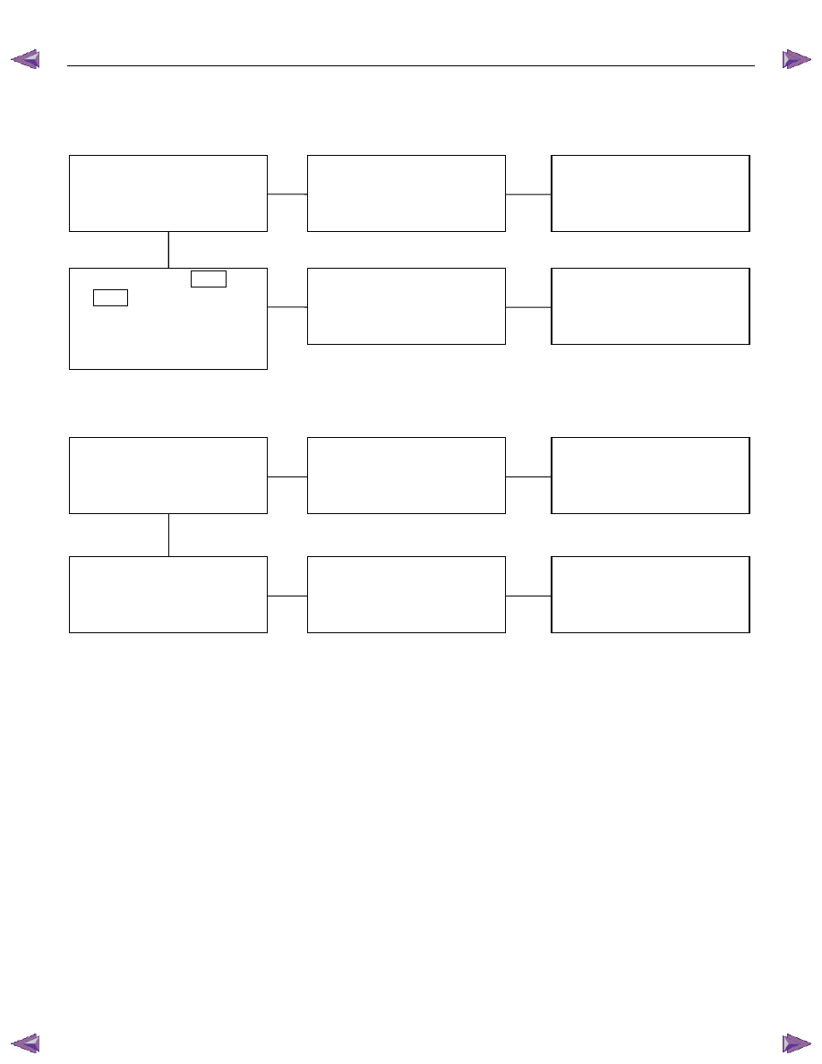
2.  One side of horn does not blow 
 

Checkpoint  

Trouble 

Cause 


Countermeasure 


Repair open circuit or 

reconnect the connector 


Open circuit or poor connector 

contact 


NG 

Voltage between 1  

C20 


(1  

C21 

) - ground with 

horn switch depressed 

(Should be battery voltage 

present) 


Replace the horn assembly 


Horn continuity between 

connectors 


Faulty horn assembly 


NG 

OK 


3.  Insufficient horn volume 
 

Clfean and/or remove the

foreign material

Stain foreign material in the

horn

NG

Horn

Recharge or replace the

battery

Battery condition

Discharged battery

NG

OK


ELECTRICAL-BODY AND CHASSIS  8A-235 


  REMOVAL AND INSTALLATION 


A Type 

RTW780SH002101 


REAR COMBINATION LIGHT 
Stoplight 

Removal 

1.  Open the tail gate. 

2.  Remove the screws of rear combination light. 

3.  Remove the rear combination light assembly. 


B Type 

RTW580SH000401 


A Type 

RTW780SH001201 


4.  Turn the bulb (1) counterclockwise to remove it. 


B Type 

RTW580SH000501 


Installation 

Follow the removal procedure in the reverse order to install the 
rear combination light. 
Pay close attention to the important points mentioned in the 
following paragraphs. 


Bulb 

Be absolutely sure that each bulb is correctly installed. 
This will prevent a poor contact and an open circuit. 
 

8A-236  ELECTRICAL-BODY AND CHASSIS 

HIGH MOUNTED STOPLIGHT 

Remove the bulb socket 

1.  Remove the high mounted stoplight ASM. 

•  Remove the screws. 
•  Disconnect the connector. 


2.  Remove the bulb socket. 

•  Turn the bulb 

1

 counterclockwise to remove it. 


Installation 

Follow the removal procedure in the reverse order to install the 
rear combination light. 
Pay close attention to the important points mentioned in the 
following paragraphs. 


Bulb 

Be absolutely sure that each bulb is correctly installed. 
This will prevent a poor contact and an open circuit. 


DOOR MIRROR - TURN SIGNAL LIGHT 

Removal 

1.  Pull the lower outside corner of the mirror toward you. 


RUW580SH000701 


2. Press the blade of an ordinary screwdriver (2) into the 

mirror outside groove near the mirror base hole (1). 

ELECTRICAL-BODY AND CHASSIS  8A-237 


RUW580SH000801 


3.  Turn the blade of the screwdriver 90 degrees to separate

the parts (1). 


RUW580SH000901 


4.  Use an ordinary screwdriver inserted into the inner groove 

(1) of the outside mirror case to pry off the outside panel (it 

pasts up on butyl tape). Do this at 5 points around the 

groove. 


RUW580SH001001 


5.  Insert an ordinary screwdriver into the inner groove (1) of 

the door mirror - turn signal light. Pry the light free. 

6.  Disconnect the connector (2). 


Installation 

Follow the removal procedure in the reverse order to install the 
door mirror - turn signal light. 
Pay close attention to the important points mentioned in the 
following paragraphs. 


SIDE TURN LIGHT 

Removal 

1.  Remove the lens 

1

•  Pull the light/bulb toward you while pushing the light

housing in the rear direction of the vehicle to release its

lock. 

•  Remove the socket by turning it counterclockwise. 

2.  Pull the bulb 

2

 to remove it. 


Installation 

Follow the removal procedure in the reverse order to install the 
side turn light. 
Pay close attention to the important points mentioned in the 
following paragraphs. 


Content   ..  1291  1292  1293  1294   ..