Content .. 1275 1276 1277 1278 ..
Isuzu KB P190. Manual - part 1277
8A-170 ELECTRICAL-BODY AND CHASSIS
FRONT TURN SIGNAL LIGHT BULB
(A type)
Removal
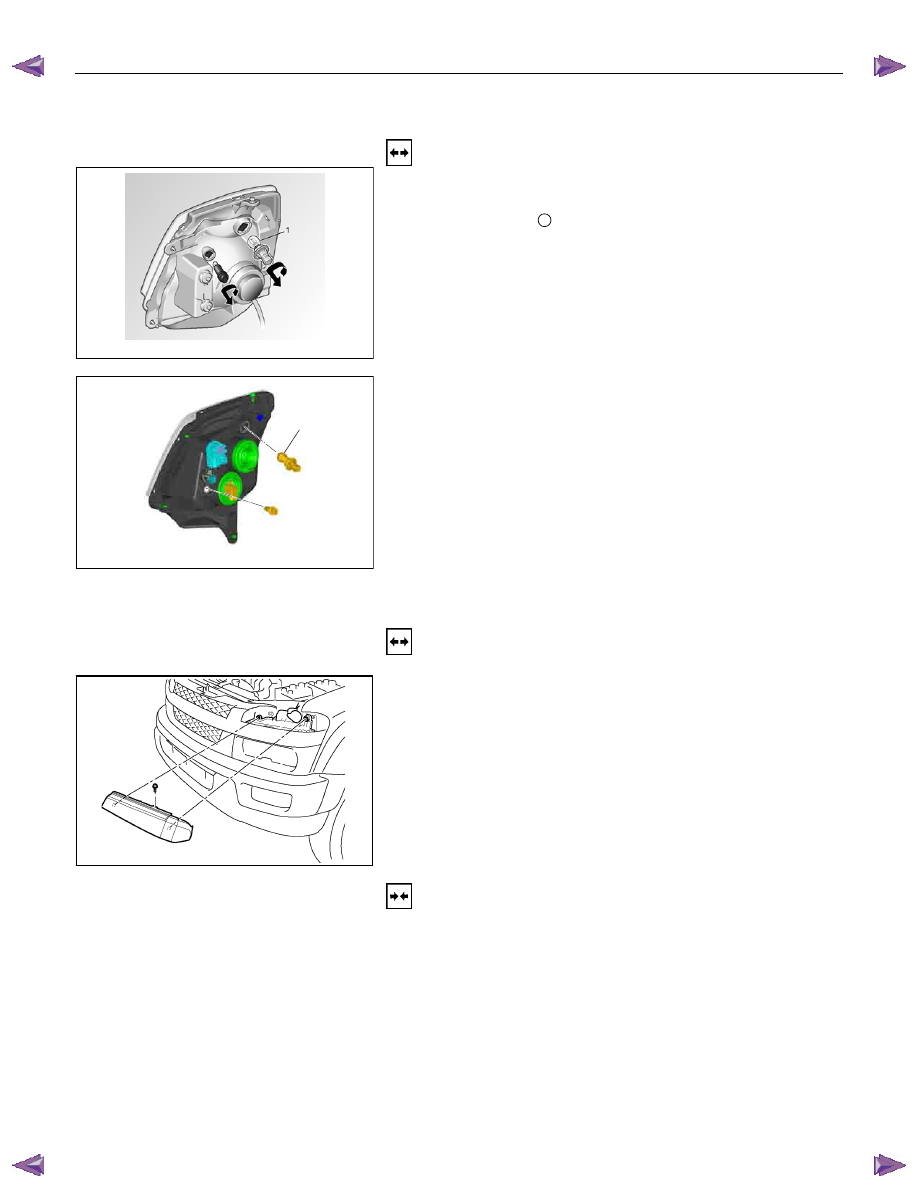
HALOGEN STD TYPE
RTW78ASH000201
1. Turn the socket counterclockwise to disconnect it from the
front turn signal light housing.
2. Turn the bulb
1
counterclockwise to remove it.
1
HALOGEN PROJECTOR TYPE
RTW78ASH001001
FRONT COMBINATION LIGHT
ASSEMBLY (B type)
Removal
1. Open the bonnet.
RTW580SH000901
2. Remove the bolt of front combination light assembly
3. Disconnect the front combination light harness connector.
4. Remove the front combination light assembly.
Installation
To install the front combination light assembly follow the
removal procedure in the reverse order.
Connector
Be absolutely sure that the front combination light harness
connector is correctly installed.
This will prevent a poor contact and an open circuit.