Content .. 1236 1237 1238 1239 ..
Isuzu KB P190. Manual - part 1238
8A-14 ELECTRICAL-BODY AND CHASSIS
Distinction of Circuit by Wire Base Color
Base color
Circuits
Base color
Circuits
B
Starter circuit and grounding circuit
Y
Instrument circuit
W
Charging circuit
L, O, BR,
R
Lighting circuit
LG, GR,
Other circuits
G
Signal circuit
P, LB, V
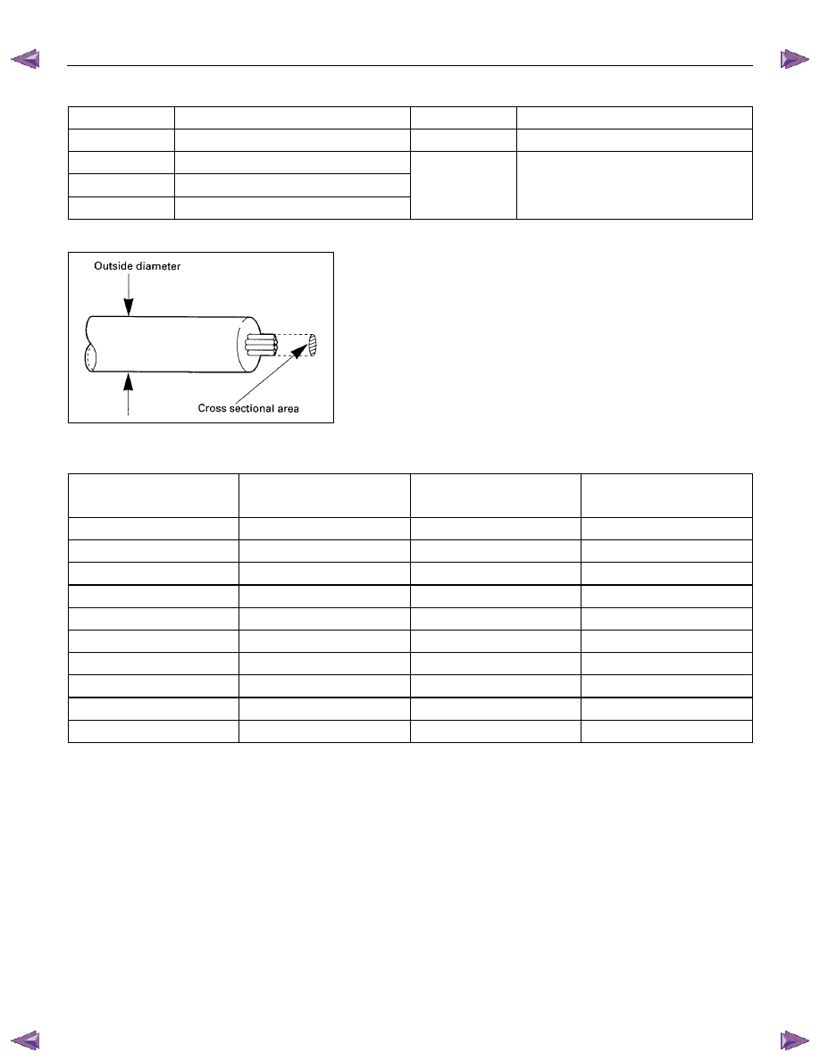
Wire Size
Wire size is specified with the metric gauge system.
The metric gauge system gives the wire size in cross sectional
area measured in square millimeters.
Wire Size Specifications
Nominal size
Cross sectional area
(mm
2
)
Outside diameter
(mm)
Allowable current
(A)
0.3 0.372 1.8
9
0.5 0.563 2.0 12
0.85 0.885 2.2
16
1.25 1.287 2.5
21
2 2.091 2.9 28
3 3.296 3.6 37.5
5 5.227 4.4 53
8 7.952 5.5 67
15 13.36 7.0 75
20 20.61 8.2 97