Isuzu KB P190. Manual - part 1120


  Index      Isuzu     Isuzu KB P190 - service repair manual 2007 year


Search            


Content   ..  1118  1119  1120  1121   ..


Isuzu KB P190. Manual - part 1120


UNIT REPAIR (JR405E)  7A4-3 


Disassembly steps 

1. Torque converter 

•  Pull the torque converter free. 

NOTE: 
Place a pan beneath the torque converter to catch 
automatic transmission fluid (ATF) spillage.
 

•  Drain the ATF from the torque converter. 


01ASSY101 


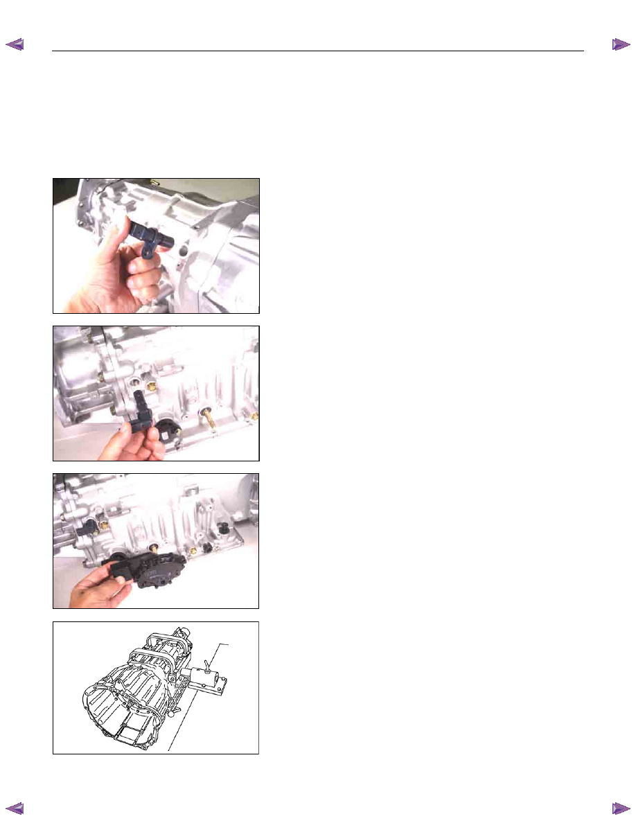
2.  Turbine sensor and speed sensor 

•  Remove the turbine sensor from the transmission case.


02ASSY103 


•  Remove the speed sensor from the transmission case.


03ASSY106 


3. Inhibitor switch 

Remove the 2 bolts and the inhibitor switch from the 

transmission case. 


240L300002 


4. Oil pan 

•  Lift and support the transmission with the holding fixture

and holding fixture base. 

Holding fixture: 5-8841-0841-0 

Holding fixture base: 5-8840-0003-0 

•  Remove the drain plug from the oil pan and drain the 

ATF from the oil pan. 

•  Rotate the automatic transmission so that the converter 

housing is facing up and drain the ATF. 

•  Rotate the automatic transmission so that the oil pan is

facing up. 

•  Remove the 19 bolts and the oil pan. 

7A4-4  UNIT REPAIR (JR405E) 


04CV37 


•  Inspect the bottom of the oil pan and strainer netting for

foreign material (clutch facing and metal shavings). 

If there is an excessive accumulation of foreign material,

the oil strainer must be replaced. 

Further inspection is required to determine the source of

the foreign material. 


45CV29 


5.  Control valve assembly 

•  Disconnect the 2 harness connectors leading to the

control valve. 


UNIT REPAIR (JR405E)  7A4-5 


244L300001 


•  Remove the 12 bolts and the control valve assembly. 


Number of bolts 

Length 


10 

(A) 

2 (B) 

40 mm (1.57 in) 
30 mm (1.18 in) 


42ASSY118 


NOTE: 
Take care not to disturb the manual valve (inside the 
control valve assembly). 
Do not allow the pin to fall free (the pin prevents the valve 
from turning). 
 

7A4-6  UNIT REPAIR (JR405E) 


10ASSY116 


6. Converter housing 

• Position the automatic transmission so that the

converter housing is facing up. 

•  Remove the 8 bolts and the converter housing. 


11ASSY068 


7. O-ring 

Remove the O-ring from the input shaft. 


12ASSY067 


8.  Oil pump assembly and bearing race 

•  Remove the 8 bolts. 
•  Use a slide hammer to remove the oil pump assembly 

from the transmission case. 

NOTE: 
To prevent damage to the oil pump bolt hole threads, 
hand-tighten the slide hammer as far as possible. 

•  Remove the bearing race from the oil pump assembly. 
•  Inspect the bearing race surfaces for damage. 


14ASSY057 


9. Input shaft 

Pull the input shaft free. 


15ASSY049 


10.Clutch pack (Reverse and high clutch assembly) and

bearing 

•  Pull the clutch pack free. 
•  Remove the bearing from the clutch pack. 


Content   ..  1118  1119  1120  1121   ..